Sign In
Upload
Manuals
Brands
Motorola Manuals
Processor
MC68340
Motorola MC68340 Integrated Processor Manuals
Manuals and User Guides for Motorola MC68340 Integrated Processor. We have
2
Motorola MC68340 Integrated Processor manuals available for free PDF download: User Manual
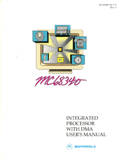
Motorola MC68340 User Manual (441 pages)
Integrated Processor with DMA
Brand:
Motorola
| Category:
Computer Hardware
| Size: 2.56 MB
Table of Contents
Table of Contents
4
Device Overview
25
Block Diagram
25
M68300 Family
26
Organization
27
Advantages
27
Central Processor Unit
27
Cpu32
28
Background Debug Mode
28
On-Chip Peripherals
29
System Integration Module
29
External Bus Interface
29
System Configuration and Protection
30
Clock Synthesizer
30
Chip Select and Wait State Generation
30
Interrupt Handling
30
Discrete I/O Pins
30
IEEE 1149.1 Test Access Port
31
Direct Memory Access Module
31
Serial Module
31
Timer Modules
32
Power Consumption Management
32
Physical
33
Compact Disc-Interactive
33
More Information
34
Signal Descriptions
35
Functional Signal Groups
35
Signal Index
36
Address Bus
38
Address Bus (A23-A0)
38
Address Bus (A31-A24)
38
Data Bus (D15-D0)
38
Function Codes (FC3-FC0)
39
Chip Selects (Cs3-Cs0)
39
Interrupt Request Level (Irq7, Irq6, Irq5, Irq3)
40
Bus Control Signals
40
Data and Size Acknowledge ( DSACK1, DSACK0 )
40
Address Strobe ( as )
40
Data Strobe ( DS )
41
Transfer Size (SIZ1, SIZ0)
41
Read/Write (R/ W )
41
Bus Arbitration Signals
41
Bus Request ( BR )
41
Bus Grant ( BG )
41
Bus Grant Acknowledge (BGACK)
41
Read-Modify-Write Cycle ( RMC )
42
Exception Control Signals
42
Reset ( RESET )
42
Halt ( HALT )
42
Bus Error ( BERR )
42
Clock Signals
42
System Clock (CLKOUT)
42
Crystal Oscillator (EXTAL, XTAL)
43
External Filter Capacitor (XFC)
43
Clock Mode Select (MODCK)
43
Instrumentation and Emulation Signals
43
Instruction Fetch (IFETCH)
43
Instruction Pipe (IPIPE)
43
Breakpoint (BKPT)
44
Freeze (FREEZE)
44
DMA Module Signals
44
DMA Request ( DREQ2, DREQ1 )
44
DMA Acknowledge (DACK2, DACK1)
44
DMA Done ( DONE2, DONE1 )
44
Serial Module Signals
45
Serial Crystal Oscillator (X2, X1)
45
Serial External Clock Input (SCLK)
45
Receive Data (Rxda, Rxdb)
45
Transmit Data (Txda, Txdb)
45
Clear to Send (CTSA, CTSB)
45
Request to Send ( RTSA , RTSB )
45
Transmitter Ready ( T RDYA )
45
Receiver Ready ( R RDYA )
46
Timer Signals
46
Timer Gate ( TGATE2, TGATE1 )
46
Timer Input (TIN2, TIN1)
46
Timer Output (TOUT2, TOUT1)
46
Test Signals
47
Test Clock (TCK)
47
Test Mode Select (TMS)
47
Test Data in (TDI)
47
Test Data out (TDO)
47
Synthesizer Power (VCCSYN )
47
System Power and Ground (VCC and GND)
47
Signal Summary
47
Bus Operation
50
Bus Transfer Signals
50
Bus Control Signals
51
Input Sample Window
51
Function Code Signals
52
Address Bus (A31-A0)
53
Address Strobe ( as )
53
Data Bus (D15-D0)
53
Data Strobe ( DS )
53
Bus Cycle Termination Signals
53
Data Transfer and Size Acknowledge Signals ( DSACK1 and DSACK0 )
53
Bus Error ( BERR )
54
Autovector ( AVEC )
54
Data Transfer Mechanism
54
Dynamic Bus Sizing
54
Misaligned Operands
56
Operand Transfer Cases
56
Byte Operand to 8-Bit Port, Odd or Even (A0 = X)
56
MC68340 Interface to Various Port Sizes
56
Byte Operand to 16-Bit Port, Even (A0 = 0)
57
Byte Operand to 16-Bit Port, Odd (A0 = 1)
58
Word Operand to 8-Bit Port, Aligned
58
Word Operand to 16-Bit Port, Aligned
59
Long-Word Operand to 8-Bit Port, Aligned
59
Long-Word Operand Read Timing from 8-Bit Port
60
Long-Word Operand to 16-Bit Port, Aligned
61
Long-Word Operand Write Timing to 8-Bit Port
61
Long-Word and Word Read and Write Timing—16-Bit Port
62
Bus Operation
63
Synchronous Operation with DSACK
63
Fast Termination Cycles
64
Fast Termination Timing
64
Data Transfer Cycles
65
Read Cycle
65
Write Cycle
67
Read-Modify-Write Cycle
68
CPU Space Cycles
70
CPU Space Address Encoding
70
Breakpoint Acknowledge Cycle
71
LPSTOP Broadcast Cycle
72
Breakpoint Operation Flowchart
73
Breakpoint Acknowledge Cycle Timing (Opcode Returned)
74
Breakpoint Acknowledge Cycle Timing (Exception Signaled)
75
Module Base Address Register Access
76
Interrupt Acknowledge Bus Cycles
76
Interrupt Acknowledge Cycle-Terminated Normally
76
Interrupt Acknowledge Cycle Flowchart
77
Autovector Interrupt Acknowledge Cycle
78
Interrupt Acknowledge Cycle Timing
78
Spurious Interrupt Cycle
79
Autovector Operation Timing
80
Bus Exception Control Cycles
81
Bus Errors
83
Bus Error Without DSACK
84
Retry Operation
85
Late Bus Error with DSACK
85
Retry Sequence
86
Halt Operation
87
Late Retry Sequence
87
Double Bus Fault
88
HALT Timing
88
Bus Arbitration
89
Bus Arbitration Flowchart for Single Request
90
Bus Arbitration Timing Diagram—Idle Bus Case
91
Bus Arbitration Timing Diagram—Active Bus Case
91
Bus Request
92
Bus Grant
92
Bus Grant Acknowledge
92
Bus Arbitration Control
93
Show Cycles
93
Bus Arbitration State Diagram
94
Reset Operation
95
Show Cycle Timing Diagram
95
Timing for External Devices Driving RESET
96
Power-Up Reset Timing Diagram
97
System Integration Module
98
Module Overview
98
Module Operation
99
Module Base Address Register Operation
99
System Configuration and Protection Operation
100
SIM40 Module Register Block
100
Internal Bus Monitor
101
Double Bus Fault Monitor
101
Spurious Interrupt Monitor
101
Software Watchdog
101
Periodic Interrupt Timer
101
System Configuration and Protection Function
102
Software Watchdog Block Diagram
104
Periodic Timer Period Calculation
105
Using the Periodic Timer as a Real-Time Clock
106
Simultaneous Interrupts by Sources in the SIM40
106
Clock Synthesizer Operation
106
Clock Block Diagram for Crystal Operation
107
MC68340 Crystal Oscillator
107
Phase Comparator and Filter
108
Clock Control
108
Clock Block Diagram for External Oscillator Operation
108
Chip Select Operation
110
Programmable Features
111
Global Chip Select Operation
111
External Bus Interface Operation
112
Port a
112
Port B
113
Full Interrupt Request Multiplexer
113
Low-Power Stop
114
Freeze
114
Programming Model
115
SIM40 Programming Model
116
Module Base Address Register (MBAR)
117
System Configuration and Protection Registers
118
Module Configuration Register (MCR)
118
Autovector Register (AVR)
120
Reset Status Register (RSR)
120
Software Interrupt Vector Register (SWIV)
121
Periodic Interrupt Timer Register (PITR)
124
Clock Synthesizer Control Register (SYNCR)
125
System Protection Control Register (SYPCR) (Note that this Register Can Only be Written
134
SIM40 Example Configuration Code
135
Overview
138
Features
139
Virtual Memory
139
Loop Mode Instruction Execution
140
CPU32 Block Diagram
140
Loop Mode Instruction Sequence
140
Vector Base Register
141
Exception Handling
141
Addressing Modes
142
Instruction Set
142
Table Lookup and Interpolate Instructions
144
Low-Power STOP Instruction
144
Processing States
144
Privilege States
144
Architecture Summary
145
Programming Model
145
User Programming Model
146
Supervisor Programming Model Supplement
146
Registers
147
Status Register
147
Instruction Set
148
M68000 Family Compatibility
148
New Instructions
148
Low-Power Stop (LPSTOP)
148
Table Lookup and Interpolation (TBL)
149
Unimplemented Instructions
149
Instruction Format and Notation
149
Instruction Word General Format
149
Instruction Summary
152
Condition Code Register
157
Data Movement Instructions
158
Integer Arithmetic Operations
159
Logic Instructions
161
Shift and Rotate Instructions
161
Bit Manipulation Instructions
162
Binary-Coded Decimal (BCD) Instructions
163
Program Control Instructions
163
System Control Instructions
164
Condition Tests
166
Using the TBL Instructions
166
Table Example 1: Standard Usage
167
Table Example 2: Compressed Table
168
Table Example 3: 8-Bit Independent Variable
169
Table Example 3
170
Table Example 4: Maintaining Precision
171
Table Example 5: Surface Interpolations
173
Nested Subroutine Calls
173
Pipeline Synchronization with the NOP Instruction
173
Processing States
173
State Transitions
174
Privilege Levels
174
Supervisor Privilege Level
175
User Privilege Level
175
Changing Privilege Level
175
Exception Stack Frame
175
Exception Vectors
176
Exception Vectors
177
Types of Exceptions
177
Exception Processing Sequence
178
Exception Stack Frame
178
Multiple Exceptions
178
Address Error
179
Bus Error
179
Reset Operation Flowchart
181
Instruction Traps
183
Software Breakpoints
183
Format Error
184
Hardware Breakpoints
184
Illegal or Unimplemented Instructions
184
Privilege Violations
185
Tracing
186
Interrupts
187
Return from Exception
188
Fault Recovery
189
Types of Faults
191
Type I-Released Write Faults
191
Type II-Prefetch, Operand, RMW, and MOVEP Faults
192
Type III-Faults During MOVEM Operand Transfer
193
Type IV-Faults During Exception Processing
193
Correcting a Fault
194
Type I-Completing Released Writes Via Software
194
Type I-Completing Released Writes Via RTE
194
Type II-Correcting Faults Via RTE
195
Type III-Correcting Faults Via Software
195
Type III-Correcting Faults by Conversion and Restart
195
Type III-Correcting Faults Via RTE
196
Type IV-Correcting Faults Via Software
196
CPU32 Stack Frames
197
Four-Word Stack Frame
197
Six-Word Stack Frame
197
Bus Error Stack Frame
197
Internal Transfer Count Register
198
Format $C—BERR Stack for Prefetches and Operands
199
Format $C—BERR Stack on MOVEM Operand
199
Development Support
200
CPU32 Integrated Development Support
200
Format $C—Four- and Six-Word BERR Stack
200
Background Debug Mode (BDM) Overview
201
Deterministic Opcode Tracking Overview
201
On-Chip Hardware Breakpoint Overview
201
In-Circuit Emulator Configuration
201
Bus State Analyzer Configuration
201
Background Debug Mode
202
Enabling BDM
202
BDM Block Diagram
202
BDM Sources
203
External BKPT Signal
203
BGND Instruction
204
Double Bus Fault
204
Command Execution
204
BDM Registers
204
Fault Address Register (FAR)
204
Return Program Counter (RPC)
204
Current Instruction Program Counter (PCC)
204
Returning from BDM
205
Serial Interface
205
BDM Command Execution Flowchart
205
CPU Serial Logic
206
Debug Serial I/O Block Diagram
207
Development System Serial Logic
208
Serial Interface Timing Diagram
208
BKPT Timing for Single Bus Cycle
209
BKPT Timing for Forcing BDM
209
BKPT /DSCLK Logic Diagram
209
Command Set
210
Command Format
210
Command Sequence Diagram
211
Command Set Summary
212
Command-Sequence Diagram
212
Read A/D Register RAREG/RDREG
213
Write A/D Register (WAREG/WDREG)
213
Read System Register RSREG
213
Write System Register WSREG
213
Read Memory Location READ
213
Write Memory Location WRITE
213
Dump Memory Block DUMP
213
Fill Memory Block FILL
213
Resume Execution GO
213
Call User Code CALL
213
Future Commands
224
Deterministic Opcode Tracking
224
Instruction Fetch ( IFETCH )
224
Instruction Pipe ( IPIPE )
224
Functional Model of Instruction Pipeline
224
Opcode Tracking During Loop Mode
225
Instruction Pipeline Timing Diagram
225
Instruction Execution Timing
226
Resource Scheduling
226
Microsequencer
226
Bus Controller Resources
226
Instruction Pipeline
227
Prefetch Controller
227
Block Diagram of Independent Resources
227
Write Pending Buffer
228
Microbus Controller
228
Instruction Execution Overlap
228
Simultaneous Instruction Execution
228
Effects of Wait States
229
Instruction Execution Time Calculation
229
Attributed Instruction Times
229
Effects of Negative Tails
230
Instruction Stream Timing Examples
231
Timing Example 1—Execution Overlap
231
Example 1—Instruction Stream
232
Example 2—Branch Taken
232
Timing Example 2-Branch Instructions
232
Example 2—Branch Not Taken
233
Example 3—Branch Negative Tail
233
Timing Example 3-Negative Tails
233
Instruction Timing Tables
234
Fetch Effective Address
236
Calculate Effective Address
237
MOVE Instruction
238
Special-Purpose MOVE Instruction
238
Arithmetic/Logic Instructions
239
Immediate Arithmetic/Logic Instructions
242
Binary-Coded Decimal and Extended Instructions
243
Single Operand Instructions
244
Shift/Rotate Instructions
245
Bit Manipulation Instructions
246
Conditional Branch Instructions
247
Control Instructions
248
Exception-Related Instructions and Operations
249
Save and Restore Operations
250
DMA Controller Module
251
DMA Block Diagram
251
DMA Module Overview
252
Single-Address Transfers
253
Dual-Address Transfer
253
DMA Module Signal Definitions
254
DMA Request ( DREQ )
254
DMA Acknowledge ( DACK )
254
DMA Done ( DONE )
254
Transfer Request Generation
254
Internal Request Generation
254
Internal Request, Maximum Rate
255
Internal Request, Limited Rate
255
External Request Generation
255
External Burst Mode
255
External Cycle Steal Mode
255
Data Transfer Modes
256
Single-Address Mode
256
DMA External Connections to Serial Module
256
Single-Address Read
257
Single-Address Read Timing (External Burst)
258
Single-Address Write
260
Single-Address Write Timing (External Burst)
260
Dual-Address Mode
262
Dual-Address Read
262
Dual-Address Write
264
DMA Channel Operation
268
Bus Arbitration
268
Channel Initialization and Startup
268
Data Transfers
269
Internal Request Transfers
269
External Request Transfers
269
Channel Termination
270
Interrupt Operation
270
Fast Termination Option
270
Fast Termination Option (Cycle Steal)
271
Register Description
272
Fast Termination Option (External Burst—Source Requesting)
272
Module Configuration Register (MCR)
273
DMA Module Programming Model
273
Interrupt Register (INTR)
276
Channel Control Register (CCR)
276
Channel Status Register (CSR)
280
Function Code Register (FCR)
282
Source Address Register (SAR)
283
Destination Address Register (DAR)
283
Byte Transfer Counter Register (BTC)
284
Data Packing
285
Packing and Unpacking of Operands
285
DMA Channel Initialization Sequence
286
DMA Channel Configuration
286
DMA Channel Operation in Single-Address Mode
287
DMA Channel Operation in Dual-Address Mode
287
DMA Channel Example Configuration Code
288
Simplified Block Diagram
296
Module Overview
297
Baud Rate Generator Logic
298
Internal Channel Control Logic
298
Interrupt Control Logic
298
Serial Communication Channels a and B
298
Comparison of Serial Module to MC68681
299
Serial Module Signal Definitions
299
Crystal Input or External Clock (X1)
300
Crystal Output (X2)
300
External and Internal Interface Signals
300
External Input (SCLK)
301
Channel a Transmitter Serial Data Output (Txda)
301
Channel a Receiver Serial Data Input (Rxda)
301
Channel B Transmitter Serial Data Output (Txdb)
301
Channel B Receiver Serial Data Input (Rxdb)
301
Channel a Request-To-Send ( RTSA )
301
Rtsa
301
Channel B Request-To-Send ( RTSB )
301
Rtsb
302
Channel a Clear-To-Send ( CTSA )
302
Channel B Clear-To-Send ( CTSB )
302
Channel a Transmitter Ready ( T RDYA )
302
T Rdya
302
Channel a Receiver Ready ( R RDYA )
302
R Rdya
302
Ffulla
302
Operation
303
Baud Rate Generator
303
Transmitter and Receiver Operating Modes
303
Baud Rate Generator Block Diagram
303
Transmitter and Receiver Functional Diagram
304
Transmitter
305
Transmitter Timing Diagram
305
Receiver
306
FIFO Stack
307
Receiver Timing Diagram
307
Looping Modes
309
Automatic Echo Mode
309
Local Loopback Mode
309
Remote Loopback Mode
309
Multidrop Mode
310
Looping Modes Functional Diagram
310
Multidrop Mode Timing Diagram
311
Bus Operation
312
Interrupt Acknowledge Cycles
312
Read Cycles
312
Register Description and Programming
312
Write Cycles
312
Serial Module Programming Model
314
Module Configuration Register (MCR)
314
Interrupt Level Register (ILR)
316
Interrupt Vector Register (IVR)
316
Mode Register 1 (MR1)
317
Status Register (SR)
319
Clock-Select Register (CSR)
321
Command Register (CR)
322
Receiver Buffer (RB)
325
Transmitter Buffer (TB)
325
Input Port Change Register (IPCR)
326
Auxiliary Control Register (ACR)
327
Interrupt Status Register (ISR)
327
Interrupt Enable Register (IER)
329
Input Port (IP)
330
Output Port Control Register (OPCR)
331
Output Port Data Register (OP)
332
Mode Register 2 (MR2)
333
Programming
335
Serial Module Initialization
335
I/O Driver Example
335
Interrupt Handling
335
Serial Module Programming Flowchart
336
Serial Module Initialization Sequence
341
Serial Module Configuration
341
Serial Module Example Configuration Code
342
Module Overview
345
Simplified Block Diagram
345
Timer and Counter Functions
346
Prescaler and Counter
346
Timeout Detection
346
Comparator
346
Clock Selection Logic
347
Internal Control Logic
347
Timer Functional Diagram
347
Interrupt Control Logic
348
Timer Modules Signal Definitions
348
Timer Input (TIN1, TIN2)
349
External and Internal Interface Signals
349
Timer Gate ( TGATE1 , TGATE2 )
350
Timer Output (TOUT1, TOUT2)
350
Operating Modes
350
Input Capture/Output Compare
350
Input Capture/Output Compare Mode
351
Square-Wave Generator
352
Square-Wave Generator Mode
352
Variable Duty-Cycle Square-Wave Generator
353
Variable-Width Single-Shot Pulse Generator
354
Variable Duty-Cycle Square-Wave Generator Mode
354
Variable-Width Single-Shot Pulse Generator Mode
355
Pulse-Width Measurement
356
Pulse-Width Measurement Mode
356
Period Measurement
357
Event Count
358
Period Measurement Mode
358
Event Count Mode
359
Timer Bypass
360
Bus Operation
361
Interrupt Acknowledge Cycles
361
Read Cycles
361
Register Description
361
Write Cycles
361
Timer Module Programming Model
362
Module Configuration Register (MCR)
362
Control Register (CR)
364
Interrupt Register (IR)
364
Status Register (SR)
367
Counter Register (CNTR)
369
Preload 1 Register (PREL1)
369
Compare Register (COM)
370
Preload 2 Register (PREL2)
370
Timer Module Initialization Sequence
371
Timer Module Configuration
371
Timer Module Example Configuration Code
372
Overview
376
TAP Controller
377
Test Access Port Block Diagram
377
Boundary Scan Register
378
TAP Controller State Machine
378
Output Latch Cell (O.latch)
382
Input Pin Cell (I.pin)
382
Active-High Output Control Cell (Io.ctl1)
383
Active-Low Output Control Cell (Io.ctl0)
383
Instruction Register
384
Bidirectional Data Cell (Io.cell)
384
General Arrangement for Bidirectional Pins
384
Extest (000)
385
Sample/Preload (001)
385
Bypass (X1X, 101)
386
Hi-Z (100)
386
MC68340 Restrictions
386
Bypass Register
386
Non-IEEE 1149.1 Operation
387
Minimum System Configuration
388
Processor Clock Circuitry
388
Minimum System Configuration Block Diagram
388
Sample Crystal Circuit
389
Statek Corporation Crystal Circuit
389
Reset Circuitry
390
SRAM Interface
390
ROM Interface
391
Serial Interface
391
Memory Interface Information
392
Using an 8-Bit Boot ROM
392
Serial Interface
392
External Circuitry for 8-Bit Boot ROM
392
Access Time Calculations
393
Bit Boot ROM Timing
393
Access Time Computation Diagram
393
Calculating Frequency-Adjusted Output
394
Signal Relationships to CLKOUT
394
Signal Width Specifications
395
Skew between Two Outputs
396
Interfacing an 8-Bit Device to 16-Bit Memory Using Single-Address DMA Mode
397
Power Consumption Considerations
397
MC68340 Power Reduction at 5V
398
MC68340 Current Vs. Activity at 5 V
398
MC68340 Current Vs. Voltage/Temperature
399
MC68340 Current Vs. Clock Frequency at 5 V
399
Mc68340V (3.3 V)
400
Thermal Characteristics
401
Power Considerations
402
AC Electrical Specification Definitions
402
Drive Levels and Test Points for AC Specifications
404
DC Electrical Specifications
405
AC Electrical Specifications Control Timing
406
AC Timing Specifications
408
Read Cycle Timing Diagram
411
Write Cycle Timing Diagram
412
Fast Termination Read Cycle Timing Diagram
413
Fast Termination Write Cycle Timing Diagram
414
Bus Arbitation Timing—Active Bus Case
415
Bus Arbitration Timing—Idle Bus Case
416
Show Cycle Timing Diagram
416
IACK Cycle Timing Diagram
417
Background Debug Mode Serial Port Timing
418
Background Debug Mode FREEZE Timing
418
DMA Module AC Electrical Specifications
419
DMA Signal Timing Diagram
419
Timer Module Electrical Specifications
420
Timer Module Clock Signal Timing Diagram
420
Timer Module Signal Timing Diagram
421
Serial Module Electrical Specifications
422
Serial Module General Timing Diagram
422
IEEE 1149.1 Electrical Specifications
424
Standard MC68340 Ordering Information
426
Pin Assignment
426
Lead Ceramic Quad Flat Pack (FE Suffix)
427
Lead Plastic Pin Grid Array (RP Suffix)
429
Package Dimensions
431
FE Suffix
431
RP Suffix
432
Advertisement
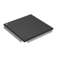
Motorola MC68340 User Manual (472 pages)
Integrated, with DMA
Brand:
Motorola
| Category:
Processor
| Size: 29.62 MB
Advertisement
Related Products
Motorola MC68306
Motorola MC68302
Motorola DragonBall MC68328
Motorola MC68360
Motorola MC68341
Motorola MC68VZ328
Motorola MC68HC908AB32
Motorola MC68020
Motorola MC68EC020
Motorola MC68HC000
Motorola Categories
Cell Phone
Two-Way Radio
Baby Monitor
Cordless Telephone
Radio
More Motorola Manuals
Login
Sign In
OR
Sign in with Facebook
Sign in with Google
Upload manual
Upload from disk
Upload from URL