Sign In
Upload
Manuals
Brands
Mitsubishi Electric Manuals
Air Conditioner
FDF100VSVD
Mitsubishi Electric FDF100VSVD Manuals
Manuals and User Guides for Mitsubishi Electric FDF100VSVD. We have
3
Mitsubishi Electric FDF100VSVD manuals available for free PDF download: Technical Manual
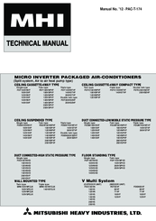
Mitsubishi Electric FDF100VSVD Technical Manual (509 pages)
Brand:
Mitsubishi Electric
| Category:
Air Conditioner
| Size: 64.42 MB
Table of Contents
1. Micro Inverter Packaged Air-Conditioners
3
V Multi System
1
Table of Contents
3
Specifications
7
Ceiling Cassette-4Way Compact Type (FDTC)
26
Ceiling Suspended Type (FDEN)
34
Duct Connected-High Static Pressure Type (FDU)
53
Duct Connected-Low/Middle Static Pressure Type (FDUM)
61
Wall Mounted Type (SRK)
88
Exterior Dimensions
89
Outdoor Units
90
Remote Controller (Option Parts)
111
Indoor Units
115
Outdoor Units
125
Noise Level
128
Characteristics of Fan
133
Temperature and Velocity Distribution
139
Piping System
148
Selection Chart
157
Ceiling Cassette-4Way Compact Type (FDTC)
167
Pac-T
175
Duct Connected-High Static Pressure Type (FDU)
181
Duct Connected-Low/Middle Static Pressure Type (FDUM)
183
Floor Standing Type (FDF)
192
Wall Mounted Type (SRK)
197
Correction of Cooling and Heating Capacity in Relation to Air Flow Rate Control (Fan Speed)
203
Application Data
205
Ceiling Cassette-4Way Compact Type (FDTC)
212
Panel Installation
216
How to Set the Airflow Direction
217
Ceiling Suspended Type (FDEN)
218
Duct Connected-High Static Pressure Type (FDU)
222
Duct Connected-Low/Middle Static Pressure Type (FDUM)
230
Floor Standing Type (FDF)
236
Wall Mounted Type (SRK)
240
Selection of Installation Location
241
Installation of Indoor Unit
241
Connection of Refrigerant Pipings
242
Electrical Wiring Work
243
Effective Range of Cool/Hot Wind (Reference)
244
Electric Wiring Work Installation
245
FDU200, 250 Series
249
FDUM Series
253
FDF Series
256
Installation of Wired Remote Controller
260
Installation Manual
266
Installation of Outdoor Unit
274
Models FDC200, 250VS
282
Refrigerant Piping Work
283
Instructions for Branching Pipe Set (DIS-WA1,WB1,TA1,TB1)
291
Outline of Operation Control by Microcomputer
294
Operation Section
296
Operation Control Function by the Wired Remote Controller
297
Operation Control Function by the Indoor Controller
300
Operations of Functional Items During Cooling/Heating
301
Timer Operation
302
Remote Controller Display During the Operation Stop
303
Thermostat Operation
304
Filter Sign
305
Operation Check/Drain Pump Test Run Operation Mode
306
Heating Overload Protection
307
High Ceiling Control
308
Operation Permission/Prohibition
310
Selection of Cooling/Heating External Input Function
311
Fan Control at Heating Startup
312
Fan Circulator Operation (RC-EX1A Only)
313
Ⅱ) SRK Seris
314
Timer Operation
315
Indoor Fan Motor Protection
316
Filter Sign
317
Operation Control Function by the Outdoor Controller
318
Compressor Soft Start Control
319
Outdoor Unit Fan Control
320
Defrosting
322
Protective Control/Anomalous Stop Control by Compressor , S Number of Revolutions
323
Silent Mode
326
Pump-Down Control
327
Maintenance Data
328
1.12.2 Troubleshooting Flow
358
Operates but Does Not Cool
360
Operates but Does Not Heat
361
Earth Leakage Breaker Activated
362
Excessive Noise/Vibration
363
Excessive Noise/Vibration
364
Excessive Noise/Vibration
365
Louver Motor Failure (FDT, FDTC, FDEN, FDF Series)
366
Power Supply System Error (Power Supply to Indoor Control PCB)
367
Power Supply System Error (Power Supply to Remote Controller)
368
INSPECT I/U (Connection of 3 Units or more Remote Controllers)
369
Communication Error at Initial Operation
371
No Display
374
Remote Controller Communication Circuit Error
375
Return Air Temperature Thermistor Anomaly
378
INSPECT I/U (When 1 or 2 Remote Controllers Are Connected)
369
E8 Heating Overload Operation
379
E10 Excessive Number of Connected Indoor Units (more than 17 Units) by Controlling with One Remote Controller
381
Communication Error between Master and Slave Indoor Units
382
Indoor Fan Motor Anomaly
383
Indoor Unit Operation Check, Drain Motor Check Setting Error
385
Indoor Fan Motor Rotation Speed Anomaly
386
E28 Remote Controller Temperature Thermistor Anomaly
388
E35 Cooling Overload Operation
389
E36 Discharge Pipe Temperature Error
390
E39 Discharge Pipe Temperature Thermistor Anomaly
393
E40 High Pressure Error (63H1 Activated)
394
Current Cut
397
2. V Multi System
454
General Information
454
V Multi System
454
Table of Models
455
Table of System Combinations
455
Specifications
456
Indoor Units
456
(A) Ceiling Cassette-4Way Type (FDT)
456
(B) Ceiling Suspended Type (FDEN)
461
Outdoor Units
466
Operation Chart
474
Application Date
477
Option Parts
478
Wireless Kit
479
FDT Series (RCN-T-36W-E)
479
Preparation before Installation
479
FDTC Series (RCN-TC-24W-ER)
481
FDEN Series (RCN-E1R)
483
FDUM,FDU,FDF Series (RCN-KIT3-E)
487
Simple Wired Remote Conroller (Rch-E3)
489
Installation of Remote Controller
489
Wiring Specifications
490
Fan Controllert Kit (U-Fcra)
495
Precautions for Wiring
495
Base Heater Kit (Cw-H-E1)
496
Installation Procedure
496
Interface Kit (Sc-Bikn-E)
502
Cable Connection for SRK Twin/Triple Installation
506
Super Link E Board (Sc-Adna-E)
507
Electrical Wiring
477
Exterior Dimensions
477
Noise Level
477
Piping System
477
Range of Usage & Limitations
477
Selection Chart
477
Temperature and Velocity Distribution
477
Advertisement
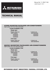
Mitsubishi Electric FDF100VSVD Technical Manual (212 pages)
Hyper/Micro Inverter Packaged Air Conditioners Floor Standing Type
Brand:
Mitsubishi Electric
| Category:
Air Conditioner
| Size: 26.69 MB
Table of Contents
Table of Contents
2
1 Specifications
4
Hyper Inverter Series
4
Micro Inverter Series
13
2 Exterior Dimensions
23
Indoor Units
23
Outdoor Units
24
3 Electrical Wiring
29
Indoor Units
29
Outdoor Units
30
4 Noise Level
36
Hyper Inverter
36
5 Temperature Distribution
38
Indoor Temperature
38
6 Piping System
39
Preset Point of the Protective Devices
41
7 Range of Usage & Limitations
42
Operating Temperature Range
43
Cooling
43
Heating
43
8 Selection Chart
45
Capacity Tables
45
Correction of Cooling and Heating Capacity in Relation to Air Flow Rate Control (Fan Speed)
55
Correction of Cooling and Heating Capacity in Relation to One Way Length of Refrigerant Piping
55
Height Difference between the Indoor Unit and Outdoor Unit
56
Piping Length Limitations
56
How to Obtain the Cooling and Heating Capacity
56
9 Application Data
57
Installation of Indoor Unit
57
Safety Precautions
57
Before Installation
58
Selection of Installation Place for the Indoor Unit
58
Carrying-In and Installation of the Unit
58
Refrigerant Piping
59
Work Procedure
59
Pipe and Wire Extracting Position
59
Backward Extraction
59
Drain Pipe
60
Wire Extracting Position and Wire Connecton
60
Control Box Position and Power Cable Connection
60
Check List after Installation
60
Electric Wiring Work Instruction
61
Security Instructions
61
Electrical Wiring Connection
61
Wiring for the Remote Controller
61
Function Setting by Remote Controller
62
How to Set Function
62
The Range of Temperature Setting
62
The Functional Setting
62
Trial Operation
63
The Method of Trial Cooling Operation
63
Checking Operation Data
64
Troubleshooting
64
Error Code of Indoor Unit
64
Control Mode Switching
64
Installation of Outdoor Unit
65
Model FDC71VNX
65
Selection of Installation Location for the Outdoor Unit
67
Caution about Selection of Installation Location
67
Refrigerant Piping Work
67
Restrictions on Unit Installation and Use
67
Determination of Pipe Size
68
Refrigerant Pipe Wall Thickness and Material
68
On-Site Piping Work
68
Air Tightness Test
69
Evacuation
69
Additional Refrigerant Charge
69
Heating and Condensation Prevention
69
Drain Piping Work
70
Electrical Wiring Work
70
Power Cables, Indoor-Outdoor Connecting Wires
70
Test Run
71
Test Run Method
71
Failure Diagnosis in a Test Run
71
Utilization of Existing Piping
72
Table of Pipe Size Restrictions
72
Pipe System after the Branching Pipe
72
Installation Manual for Outdoor Unit
73
Models FDC100~140VN,100~140VS,100~140VNX,100~140VSX
73
Drain Piping Work
75
Electrical Wiring Work
75
Test Run
76
Models FDC200,250VS
77
On Site Piping Work
80
Parts Used for the Connecting Pipe Assembly
84
Length of the Straight Pipe
84
About Brazing
84
Method for Connecting the Accessory Pipe (Models FDC200,250 Only)
84
Branching Pipe Set Specifications
86
Posture to Install into
86
Pipe Connecting Procedure
86
Instructions for Branching Pipe Set (DIS-WA1,WB1,TA1,TB1)
86
10 Outline of Operation Control by Microcomputer
88
Remote Controller (Model:rc-E4)
88
CPU Reset
89
Operation Control Function by the Wired Remote Controller
89
Power Failure Compensation Function
89
Switching Sequence of the Operation Mode Switches of Remote Controller
89
Auto Operation
90
Dehumidifying Operation
90
Operation Control Function by the Indoor Controller
90
Operations of Functional Items During Cooling/Heating
90
OFF Timer
91
Sleep Timer
91
Timer Operation
91
Weekly Timer
91
Fan Control During the Heating Thermostat off
92
Hot Keep
92
Thermostat Operation
92
3-Minute Timer
93
Compressor Inching Prevention Control
93
Filter Sign
93
Indoor Heat Exchanger Anti-Frost (Frost Protection)
93
First Detection of Heating Overload
94
Heating Overload Protection
94
Anomalous Fan Motor
95
Display to the Remote Controller
95
High Ceiling Control
95
Operation Permission/Prohibition
96
External Input/Output Control (Cnt)
97
In Case of “Pulse Input” Setting (Local Setting)
97
Output for External Control (Remote Display)
97
Remote Operation Input
97
Remote Operation
98
Return Air Temperature Compensation
99
Room Temperature Detection Temperature Compensation During Heating
99
Operation Control Function by the Outdoor Controller
100
(Ⅰ) Micro Inverter Series
100
Cooling/Dehumidifying Operation
100
Determination of Compressor Speed (Frequency)
100
Compressor Soft Start Control
101
Low Frequency Operation Control During Heating
101
Fan Tap Control During Cooling/Defumidifying Operation
102
Fan Tap Control During Heating Operation
102
Outdoor Unit Fan Control
102
Outdoor Unit Fan Tap and Fan Motor Speed
102
Caution at the Outdoor Unit Fan Start Control
103
Outdoor Unit Fan Control by Power Transistor Radiator Fin Temperature
103
Snow Protection Fan Control
103
Defrosting End Conditions
104
Defrosting Start Conditions
104
Anomalous Stop Control
105
Compressor Discharge Pipe Temperature Protection
105
Cooling High Pressure Protection
105
Protective Control
105
Anomaly Detection Control by the High Pressure Switch (63H1)
106
Compressor Pressure Ratio Protection Control
106
Heating High Pressure Protection
106
Low Pressure Control
106
Anomalous Inverter PCB
107
Anomalous Power Transistor Current
107
Over-Current Protection Current Safe Controls I, II
107
Power Transistor Temperature Protection
107
Anomalous Stop by the Compressor Start Stop
108
Dewing Prevention Control
108
Fan Motor Error
108
Refrigerant Quantity Shortage Protection
108
Control Ending Conditions
109
Pump-Down Control
109
Silent Mode
109
Base Heater off Conditions
110
Base Heater on Conditions
110
Base Heater ON/OFF Output Control (Option)
110
(Ⅱ) Hyper Inverter Series
111
Compressor Start Control
112
Low Frequency Operation Control During Cooling/Dehumidifying
112
11 Maintenance Data
121
Diagnosing of Microcomputer Circuit
121
Selfdiagnosis Function
121
Display Sequence of Error Codes or Inspection Indicator Lamps
123
Occurrence of One Kind of Error
123
Occurrence of Plural Kinds of Error
123
Troubleshooting Procedure
124
Troubleshooting at the Indoor Unit
124
Instruction of How to Replace Indoor Unit Power Pcb
125
DIP Switch Setting List
126
Troubleshooting at the Outdoor Unit
127
Module of Part to be Replaced for Outdoor Unit Controller
127
Replacement Procedure of Outdoor Control PCB
127
Precautions for Safety
127
Outdoor Inverter PCB Replacement Procedure
133
Check of Anomalous Operation Data with the Remote Controller
140
Power Transistor Module (Including the Driver PCB) Inspection Procedure
141
Inverter Checker for Diagnosis of Inverter Output
142
Outdoor Unit Controller Failure Diagnosis Circuit Diagram
143
Troubleshooting Flow
149
Pac-T
161
Communication Error
171
Indoor Fan Motor Anomaly
172
Indoor Unit Operation Check
173
Indoor Fan Motor Rotation Speed Anomaly
174
Remote Controller Temperature Thermistor Anomaly
175
Cooling Overload Operation
176
Discharge Pipe Temperature Error
177
Outdoor Heat Exchanger Temperature Themistor Anomaly
178
Outdoor Air Temperature Thermistor Anomaly
179
Discharge Pipe Temperature Thermistor Anomaly
180
High Pressure Error (63H1 Activated)
181
Power Transistor Overheat
182
Current Cut
184
Communication Error between Inverter PCB and Outdoor Control PCB
186
Inverter PCB A/F Module Anomaly
187
Outdoor Fan Motor Anomaly
188
Inverter and Fan Motor Anomaly
191
Suction Pipe Temperature Thermistor Anomaly
192
Low Pressure Sensor Anomaly
193
Underneath Temperature Thermistor Anomaly
194
12 Option Parts
198
Wireless Kit (RCN-KIT3-E)
198
Option Parts
199
Wireless Kit
199
How to Install the Receiver
199
Drilling of the Ceiling (Ceiling Opening)
199
Simple Wired Remote Conroller (RCH-E3)
200
Installation of the Controller Holder
200
Control Plural Indoor Units with One Remote Controller
200
Master/Slave Setting When Using Plural Remote Controller
200
Simple Wired Remote Controller
201
Names and Functions of Sections
201
Installation of Remote Controller
201
Remote Control Installation Dimensions
202
In Case of Embedding Wiring
202
In Case of Exposing Wiring
202
Wiring Specifications
202
In Case of Exposing Cord
203
In Case of Embedding Cord
203
Installation and Wiring of Remote Controller
203
The Indication When Power Source Is Supplied
204
Confirmation Method for Return Air Temperature
204
Function Setting
205
Function Setting Item by Switch on PCB
205
How to Set Functions by Button Operation
206
Base Heater Kit (CW-H-E)
206
Installation Procedure
207
Mitsubishi Electric FDF100VSVD Technical Manual (210 pages)
Brand:
Mitsubishi Electric
| Category:
Air Conditioner
| Size: 9.04 MB
Table of Contents
Table of Contents
2
1 Specifications
4
Hyper Inverter Series
4
Micro Inverter Series
13
2 Exterior Dimensions
23
Indoor Units
23
Outdoor Units
24
3 Electrical Wiring
29
Indoor Units
29
Outdoor Units
30
4 Noise Level
36
5 Temperature Distribution
38
6 Piping System
39
7 Range of Usage & Limitations
42
8 Selection Chart
45
Capacity Tables
45
Correction of Cooling and Heating Capacity in Relation to Air Flow Rate Control (Fan Speed)
55
Correction of Cooling and Heating Capacity in Relation to One Way Length of Refrigerant Piping
55
Height Difference between the Indoor Unit and Outdoor Unit
56
9 Application Data
57
Installation of Indoor Unit
57
Electric Wiring Work Instruction
61
Installation of Outdoor Unit
65
Model FDC71VNX
65
Models FDC100 140VN,100 140VS,100 140VNX,100 140VSX
73
Models FDC200,250VS
77
Method for Connecting the Accessory Pipe (Models FDC200,250 Only)
84
Instructions for Branching Pipe Set (DIS-WA1,WB1,TA1,TB1)
86
10 Outline of Operation Control by Microcomputer
88
Remote Controller
88
Operation Control Function by the Remote Controller
89
Operation Control Function by the Indoor Controller
90
Operation Control Function by the Outdoor Controller
100
) Micro Inverter Series
100
) Hyper Inverter Series
111
11 Maintenance Data
121
Diagnosing of Microcomputer Circuit
121
Selfdiagnosis Function
121
Troubleshooting Procedure
124
Troubleshooting at the Indoor Unit
124
Troubleshooting at the Outdoor Unit
127
Check of Anomalous Operation Data with the Remote Controller
140
Power Transistor Module (Including the Driver PCB) Inspection Procedure
141
Inverter Checker for Diagnosis of Inverter Output
142
Outdoor Unit Controller Failure Diagnosis Circuit Diagram
143
Troubleshooting Flow
149
Operates but Does Not Cool
150
Operates but Does Not Heat
151
None Earth Leakage Breaker Activated
152
None Excessive Noise/Vibration (1/3)
153
None Excessive Noise/Vibration (2/3)
154
None Excessive Noise/Vibration (3/3)
155
None Power Supply System Error (Power Supply to Indoor Control PCB)
156
None Power Supply System Error (Power Supply to Remote Controller)
157
INSPECT I/U (When 1 or 2 Remote Controllers Are Connected)
158
INSPECT I/U (Connection of 3 Units or more Remote Controllers)
159
Initial Operation (2/3)
161
WAIT Communication Error at Initial Operation 159
162
Applicable Model
163
Condition of Error Displayed
163
Error Detection Method
163
None no Display
163
Presumable Cause
163
Troubleshooting
163
E1 Remote Controller Communication Circuit Error
164
Countermeasure
165
E5 Communication Error During Operation
165
Yes
165
E6 Indoor Heat Exchanger Temperature Thermistor Anomaly
166
E7 Return Air Temperature Thermistor Anomaly
167
E8 Heating Overload Operation
168
E10 Excessive Number of Connected Indoor Units (more than 17 Units) by Controlling with One Remote Controller
169
E14 Communication Error between Master and Slave Indoor Units
170
E16 Indoor Fan Motor Anomaly
171
E19 Indoor Unit Operation Check
172
E20 Indoor Fan Motor Rotation Speed Anomaly
173
E28 Remote Controller Temperature Thermistor Anomaly
174
Defective Outdoor Control PCB Replace
175
E35 Cooling Overload Operation
175
Defective Outdoor Control PCB Replace
176
E36 Discharge Pipe Temperature Error
176
E37 Outdoor Heat Exchanger Temperature Thermistor Anomaly
177
E38 Outdoor Air Temperature Thermistor Anomaly
178
E39 Discharge Pipe Temperature Thermistor Anomaly
179
E40 High Pressure Error (63H1 Activated)
180
E41 Power Transistor Overheat
181
Current Cut
183
E45 Communication Error between Inverter PCB and Outdoor Control PCB
185
E47 Inverter PCB A/F Module Anomaly (Model FDC 71 Only)
186
Outdoor Fan Motor Anomaly
187
Low Pressure Error or Low Pressure Sensor Anomaly
188
E51 Inverter and Fan Motor Anomaly
190
E53 Suction Pipe Temperature Thermistor Anomaly
191
E54 Low Pressure Sensor Anomaly
192
E55 Underneath Temperature Thermistor Anomaly (Models FDC 200, 250 Only)
193
E57 Insufficient Refrigerant Amount or Detection of Service Valve Closure
194
Compressor Startup Failure
195
E60 Compressor Rotor Lock Error (Models FDC 200, 250 Only)
197
12 Option Parts
198
Wireless Kit (RCN-KIT3-E)
198
Simple Wired Remote Conroller (RCH-E3)
200
Base Heater Kit (CW-H-E)
206
Advertisement
Advertisement
Related Products
Mitsubishi Electric FDF100VNVD
Mitsubishi Electric FDF100VNXVD
Mitsubishi Electric FDF100VSXVD
Mitsubishi Electric FDF100VD
Mitsubishi Electric FDF125VNVD
Mitsubishi Electric FDF125VSVD
Mitsubishi Electric FDF140VSVD
Mitsubishi Electric FDF140VSPVD
Mitsubishi Electric FDF125VNXVD
Mitsubishi Electric FDF125VSXVD
Mitsubishi Electric Categories
Air Conditioner
Controller
Projector
Inverter
Heat Pump
More Mitsubishi Electric Manuals
Login
Sign In
OR
Sign in with Facebook
Sign in with Google
Upload manual
Upload from disk
Upload from URL