Sign In
Upload
Manuals
Brands
IBM Manuals
Storage
TS1150
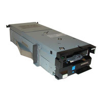
IBM TS1150 Tape Drive Storage Manuals
Manuals and User Guides for IBM TS1150 Tape Drive Storage. We have
1
IBM TS1150 Tape Drive Storage manual available for free PDF download: Maintenance Information
IBM TS1150 Maintenance Information (362 pages)
Rack Mount Models
Brand:
IBM
| Category:
Storage
| Size: 7.64 MB
Table of Contents
Read this First
2
Table of Contents
4
List of Figures
10
Information Website Urls
18
Preface
18
Related Information
18
3584 Information
18
Fibre Channel Attachment Information
18
Website Information
18
Chapter 1. Start
21
Maintenance Starting Point
21
Start here
21
CE Logs Menu (CE Offline Mode)
23
FID Entry Point
26
Updating Microcode
26
Fids and Frus
27
Attention Drive (ATTN DRV) Messages
31
ATTN DRV Messages
31
Tapealert Reporting
32
Chapter 2. Introduction
39
3592 Introduction
39
RAS Characteristics
40
Minimum Installation Configuration
40
Reliability
41
Availability
41
Serviceability
41
Maintenance Strategy
42
FID Strategy
42
Host Messages
42
Federal Information Processing Standards (FIPS)
43
Device Characteristics
44
Fibre Channel Connectivity
44
Tape Cartridge
45
Cartridge Type Indicator
45
3592 Data Tape Cartridge
45
Tape Cartridge
46
Cartridge Capacity Scaling
47
Cartridge Memory (CM)
47
Write-Once Read-Many (WORM)
47
Tape Drive
48
Drive Layout
48
Operator Bezel
48
Operator Bezel - Drive Canister Front View
49
Drive Rear Layout
50
Drive Rear Layout - Models EH7/EH8/55F/60F (Fibre Channel)
50
LED Locations for EH7/EH8/55F/60F
51
Power Supplies
52
Power Distribution Diagram
53
Power Switch and Power Sequence
54
Power Cords
54
Power Specifications
54
Redundant Power
55
Subsystem Initialization
55
Initial Microprogram Load (IML)
55
Power Sequencing
55
Subsystem Diagnostic Tests
55
Field Microcode Update
55
Special Tools and Customer Supplies
55
Cleaning Cartridge
56
Special Tools and Customer Supplies
56
Leader Pin Replacement Kit
56
Leader Pin Replacement Kit
57
Cleaning Cartridge
57
ESD Kit
58
Tape Unit Cleaner
58
Hook-And-Loop Fastener
58
Fibre Wrap Tool
58
Chapter 3. Messages
59
Service and Media Information Messages (Sims and Mims)
59
Sims
59
SIM Error Information
59
SIM Format - Sample
60
Mims
61
MIM Error Information
61
MIM Format - Sample
62
Statistical Analysis and Reporting System (SARS)
63
Hexadecimal-To-ASCII Conversion
63
Obtaining Drive Error Information at Host
64
Error Log on Host Display
64
Message Codes
65
MIM Exception Messages
66
SIM Exception Messages
66
SIM/MIM Service Messages
66
MIM Exception Messages and Descriptions
66
SIM Exception Messages and Descriptions
66
SIM/MIM Severity
67
Sense Keys, ASC, and ASCQ Information
67
Sense Key 0 (no Sense)
67
SIM/MIM Service Messages and Descriptions
67
SIM/MIM Severity Descriptions
67
ASC, and ASCQ Summary for Sense Key 0 (no Sense)
67
Sense Key 1 (Recovered Error)
68
Sense Key 2 (Not Ready)
68
Sense Key 3 (Medium Error)
68
ASC, and ASCQ Summary for Sense Key 1 (Recovered Error)
68
ASC, and ASCQ Summary for Sense Key 2 (Not Ready)
68
ASC, and ASCQ Summary for Sense Key 3 (Medium Error)
68
Sense Key 4 (Hardware Error)
70
Sense Key 5 (Illegal Request)
70
ASC, and ASCQ Summary for Sense Key 4 (Hardware Error)
70
ASC, and ASCQ Summary for Sense Key 5 (Illegal Request)
70
Sense Key 6 (Unit Attention)
72
Sense Key 7 (Data Protect)
72
ASC, and ASCQ Summary for Sense Key 6 (Unit Attention)
72
ASC, and ASCQ Summary for Sense Key 7 (Data Protect)
72
Sense Key 8 (Blank Check)
73
Sense Key B (Aborted Command)
73
Sense Key D (Volume Overflow)
73
Error Log Analysis - AIX
73
ASC, and ASCQ Summary for Sense Key 8 (Blank Check)
73
ASC, and ASCQ Summary for Sense Key B (Aborted Command)
73
ASC, and ASCQ Summary for Sense Key D (Volume Overflow)
73
Tapeutil Command
74
Diag Command
74
Analyzing Tapeutil and Diag Command Error Log
74
AIX TAPEUTIL and DIAG Commands Error Log Example
75
AIX TAPEUTIL and DIAG Commands SIM Error Log Example
75
Tapeutil Errors
76
AIX TAPEUTIL and DIAG Commands MIM Error Log Example
76
AIX TAPEUTIL and DIAG Commands Error Log Example
76
Device Driver to AIX ERRNO Translation
77
SMIT Command
78
ERRPT Command
78
SMIT/ERRPT Errors
78
AIX SMIT and ERRPT Command Error Log Example
79
Error Log Example of SIM Message - AIX
80
Error Log Example of MIM Message - AIX
81
AIX SMIT and ERRPT Command Error Log Example
82
Error Log Analysis - System I
83
AIX SMIT and ERRPT Commands Error Log Example - Descriptions
83
System I with RISC Processor
84
System I Example Error Log of SIM Message
84
System I Hexadecimal Error Log (Display)
86
System I (AS/400) Product Activity Log (Display)
87
Obtaining Drive Error Information from Linux System
88
System I Hexadecimal Error Log (Printout)
88
Forcing a Drive Dump
89
Reading a Dump
89
Automatically Retrieved SIM/MIM Data
89
Error Log Analysis - Linux System
89
Obtaining Drive Error Information from Solaris System
90
Obtaining Drive Error Information from HP-UX System
91
Obtaining Drive Error Information from Windows System
91
Running NTUTIL
91
NTUTIL Symbolic Error and Error Number
91
SCSI Sense Data
93
Chapter 4. Virtual Operator Panel
97
Virtual Operator Panel
97
Virtual Operator Panel Indicators, Icons, and Message Areas
97
Virtual Operator Panel Controls
97
Virtual Operator Panel Display
98
Virtual Operator Panel Controls
98
Virtual Operator Panel Display - Menu, Status, and Message Areas
99
Virtual Operator Panel Display - Menu, Status, and Message Areas
101
Drive Type and Capability Indicator
102
Media Data Indicator
102
Horizontal Bar Indicators
103
Clean Icon
103
Dump Icons
103
Write-Protected Icons
104
Intervention Messages
104
Intervention Screen, Mount Screen, and Abend Screen on Service Panel
105
Virtual Operator Panel Menus
107
Virtual Operator Panel 87
107
Virtual Operator Panel Menu Trees
108
Confirm Mode Change and CE Online Mode Menus
109
Virtual Operator Panel Menu Trees Guide
109
CE Disp Sensors Menu
109
Operator Options Menus - Operator Mode
110
Services Menu
110
Set Online Menu
110
CE Options Menu - CE Offline Mode (Part 1 of 6)
111
CE Options Menu - CE Offline Mode (Part 2 of 6)
112
CE Default Density Menu
112
CE DRV Features Menu
112
CE Options Menu - CE Offline Mode (Part 3 of 6)
113
CE Disp/Alt VPD Menu
113
CE Options Menu - CE Offline Mode (Part 4 of 6)
114
CE Select Address Menu
114
CE Options Menu - CE Offline Mode (Part 5 of 6)
115
CE Verify Fix/Diag Menu
115
CE Loop Diag Menu
115
Confirm Mode Change Menu
116
CE Options Menu - CE Offline Mode (Part 6 of 6)
116
DRV Encryption Menu
116
BOP Encryption Menu
116
Operator Mode Menus
117
Microcode Level Menu
118
Confirmation Menu
119
Set Offline Menu
119
Confirm Offline Menu
120
Fibre Options Menu (Services Menu)
120
Port/Node Names Menu (Services Menu)
121
Set Port 0 {Or 1} (Speed) Menu
122
Use Soft Address Menu
122
Set Topology Menu - Speed and Topology
123
Set Port 0 {Or 1} Menu (Services Menu)
124
Set Hard Address Menu
124
Statistics Menu (Operator Mode)
126
Drive Statistics Menu (Operator Mode)
126
CE Offline Mode Menus
127
Tape Statistics Menu (Operator Mode)
127
CE Options Menu (CE Offline Mode)
128
Status Menu
130
CE Action Successful Display
131
CE Action Failed Display
131
Test Fibre Wrap Menu
131
CE Dump Menu
133
CE Copy Dump to Tape Menu
134
CE FMR Tape Menu
135
Load FMR Tape Menu
135
CE Select Level Menu
135
Load Scratch Tape Menu
137
Unload Tape Menu
138
CE Config/Install Menu
138
Method Config Menu (Encryption)
141
Advanced Config Menu (Encryption)
141
Restore Defaults Menu (Encryption)
141
CE Save Data Menu (Encryption)
142
Crypto Officer Menu (Encryption)
144
Key Path Config Menu (Encryption)
144
CE Save Data Menu (Root, Port, and Node Names)
146
CE Wrap Tools Menu
147
CE VPD Data Menu
147
CE Save Data Menu (Ser No)
148
Fibre Options Menu (CE Offline Mode)
149
Port/Node Names Menu (CE Offline Mode)
149
Set Root Name Menu (CE Offline Mode)
150
Set Port 0 {Or 1} Name Menu
151
Set Node 0 {Or 1} Name Menu
151
Restor Orig Names Menu (CE Offline Mode)
152
CE Error Log Menu
154
Time Stamp for CE Error Log
155
CE FID FE Log Menu
155
CE FID FF Log Menu
157
CE Temp Error Log Menu
157
CE Utilities Menu
158
CE Read Tape Menu
158
CE Microcode Traps Menu
160
CE Saved Traps Menu
160
CE FSC Trap List Menu
160
CE Process Tape Menu
162
Space Menu
163
Read Block Menu
163
Next Block ID Menu
164
Enter Password Menu
164
CE Engr Use Only Menu
165
HSARS Config Menu
166
VSARS Config Menu
167
Special Modes Menu
167
OEM Use Only Menu
168
Show Statistics Menu (CE Offline Mode)
168
Display Memory Menu
169
Display/Alter Menu
170
CE Online Mode Menus
171
Saved FSC Trap List Menu (CE Offline Mode)
171
CE Online Options Menu (CE Online Mode)
172
CE Logs Menu (CE Online Mode)
172
CE DRV Ser no Menu (CE Online Mode)
173
Tape Statistics Menu (CE Online Mode)
175
Chapter 5. Safety and Inspection
176
General Instructions
176
Materials Needed
176
Education
176
Safety
176
Safety Inspection Procedure
177
Labels
178
Label Locations
179
Enclosure Label Locations (Top of Enclosure Shown)
180
Enclosure Label Names and Locations
180
Completion Report
181
Completion Report (Additional Copy)
182
Completion Report (Additional Copy)
183
Completion Report (Additional Copy)
184
Completion Report (Additional Copy)
185
Sécurité
186
Inspection de Sécurité
186
Seguridad
186
Procedimiento de Inspección de Seguridad
187
Segurança
187
Procedimentos para Inspeção de Segurança
187
Chapter 6. Installation
188
Before Installation
188
Installation Instruction Feature Codes and Rpqs
188
Tools
189
Installing the Rack Mount Kit
189
Exploded Rack Mount View
190
Installing the Rail - Front
191
Installing the Rail - Rear
191
Lock/Unlock Positions
192
Securing the Drive Cable with the Retention Strap
193
Installation Checkout
194
Setting Customer Options
195
Drive Canister Leds (EH8 Fibre Channel)
195
Drive Canister Leds
195
Setting Drive Options
196
Running Tests
197
Fibre Channel Attachments
197
Supported Host Attachments
197
Fibre Channel Cabling Examples
198
Feature Codes - Fibre Channel Attachment with LC/LC Cables
198
Fibre Channel Cable at Host
199
Online Testing
199
Post-Installation Reporting and Activities
200
Removing the Drive from Service
200
Relocating or Storing the Drive
200
Repacking Instructions
201
Chapter 7. Procedures
202
Problem Determination
202
Excessive Clean Messages
203
Preparing the Tape Drive for Service
203
Powering the Device on and off
203
Removing Drive Canister Power
203
Restoring Drive Canister Power
204
End of Call
205
Verifying the Fix
205
Setting the Device Online
205
Final Checks
205
Connecting and Disconnecting the Laptop from the Drive
206
Enclosure - Front View, Showing the Bezel Removed and the Ethernet Ports (Circled)
206
Ethernet (Laptop) Drive Dump Procedures
207
Determining Current Dump Status
207
Offloading Microcode Dumps with the Front Ethernet Port
208
Ethernet (Laptop) Microcode Procedures
209
Determining Current Drive Microcode Level
209
Updating Microcode with the Ethernet Port
209
Obtaining Microcode Image with the Ethernet Port
209
Drive FRU VPD Procedures
210
Displaying the Drive Status Page
211
Electrostatic Discharge (ESD) Sensitive Parts
212
Static-Sensitive Device Attention Symbol and Grounding Wrist Strap
212
Cleaning the Operator Bezel
213
Power Problems MAP
213
Step Power 01
214
Step Power 02
214
Step Power 03
214
Step Power 04
214
Step Power 05
214
Step Power 06
215
Manual Cartridge Removal
215
Drive Canister - Canister Screws
217
Tape Spooled off Supply Reel
218
Tape Pulled from Leader Pin or Broken Near Leader Pin
219
Drive Canister with Cover Removed to Reveal Gear Train
220
Tape Broken in Midtape
221
Tape Tangled Along Tape Path
222
No Apparent Failure or Damage to Tape
223
FMR Tape Maintenance
224
Making FMR Tape from CE Scratch Tape
224
Updating FMR Tape from the Drive
224
Updating Microcode from the FMR Tape Cartridge
224
Converting FMR Tape to a CE Scratch Tape
225
History Log Examples
225
Microcode EC Level History Log
225
Fibre Channel Worldwide Names History Log
226
Microcode Level Menu
226
Microcode EC Level History Log
226
Node Name Menu
227
Fibre Channel WWID History Log Example and Worksheet
227
Alter Serial no - CE VPD Data Menu
228
Alter Serial no - CE Save Data? Menu
228
CE Set Node 1 Name Menu
229
Setting Root Names
230
Dump Maintenance Utilities
230
Offloading Dumps
230
Offloading the Dump to Flash Memory
231
Offloading Dumps to System I (OS/400)
232
Offloading Dumps to AIX with TAPEUTIL
232
Offloading Dumps to Linux System with TAPEUTIL
233
Offloading Dumps to Solaris System with TAPEUTIL
234
Offloading Dumps to HP-UX System with TAPEUTIL
235
Offloading Dumps to Windows System with NTUTIL
236
Offloading Dumps to Tape Cartridge
236
Microcode Maintenance
237
Updating Microcode from System I (OS/400)
237
Updating Microcode from AIX with TAPEUTIL
238
Updating Microcode from Linux with TAPEUTIL
239
Updating Microcode from Solaris with TAPEUTIL
240
Updating Microcode from HP-UX System with TAPEUTIL
241
Updating Microcode from Windows with NTUTIL
242
Updating Microcode with an FMR Cartridge
242
Starting NT UTILITY (Ntutil) from Windows
242
Exercising Drive Attached to Windows with NTUTIL
244
Base Mode
244
Host Attachment Checkout
245
Checking Channel Attachment - System I (OS/400)
245
Checking Channel Attachment - AIX
245
Host Attachment Example
246
Device Fibre Addresses - Available
246
Device Fibre Addresses - Defined
246
Checking Channel Attachment - Linux
249
Checking Channel Attachment - Solaris
250
Checking Channel Attachment - HP-UX
252
Checking Channel Attachment - Windows
254
Checking Channel Attachment with NTUTIL under Windows
256
Fibre Channel Testing
256
Fibre Wrap Test
256
Fibre Channel Problem Determination
257
FID 83 or E5 - Microcode Problem
259
FID 84 or E6 - Isolating Fault between Microcode and Hardware
260
FID 84 or E6 - Normal FID Display Procedure
261
FID 84 or E6 - Smaller Font (Abnormal Display Condition)
262
FID 87 or F2 - Isolating Fault between Media and Hardware
263
FID FF - Operator Action or Host Program Error
265
FID FF Displayed on Service Panel and Message Display
265
FID FF Displayed at Host Only - Not on Service Panel or Message Display
265
Suspected Microcode Problem
266
Setting the Error Match Trap (to Get Dump)
266
Removing the Error Match Trap
267
Removing a NORMAL Trap
268
Removing a SAVED Trap
268
Setting Default Density
269
Default Density Selections
269
Setting Drive Encryption
270
Chapter 8. Locations, Checks, Adjustments, Removals, and Replacements
271
Rack FRU Locations, Removals, and Replacements
271
FID 82: Power Supply
272
FID 85: Drive Canister
272
Drive Canister Connectors
273
Front of the Drive Canister, Showing the Spring Plunger
274
FID EA: Cables FRU Kit
275
Ferrite Beads on the Cable Assembly
276
Removing the Power Supply Bracket
277
Removing the Enclosure from a Rack
278
Chapter 9. Parts Catalog Information
279
3592 EH7/EH8/55E/55F/60F Rack FRU List
279
Exploded Rack Mount View
279
Appendix A. ITDT Support
281
TAPEUTIL in Sun (Solaris) System Environment
283
TAPEUTIL Program Menu - Sun Solaris System
284
Service Commands and Syntax
284
Basic SCSI Commands and Syntax
285
Medium Changer Commands and Syntax
285
Tape Drive Commands and Syntax
285
Service Commands and Syntax
285
Tape Drive Commands and Syntax
286
TAPEUTIL in HP-UX System Environment
289
Introduction
289
Interactive Menu-Driven Interface
289
Command-Line Mode
290
Command-Line Commands and Syntax
290
TAPEUTIL Program Menu - HP-UX System
290
Basic SCSI Commands and Syntax
291
Medium Changer Commands and Syntax
291
Flag Descriptions
292
Examples
293
TAPEUTIL in Windows System Environment (NTUTIL)
295
NT Utility Program
295
Starting NTUTIL
295
Interactive Mode
295
Base Mode
296
Library Mode
296
Library Mode: Windows Environment
297
TAPEUTIL in Linux System Environment
298
Ibmtapeutil Run Procedure
298
Interactive Mode
298
TAPEUTIL Program Commands Menu - Linux Environment (Interactive Mode Command)
299
Command-Line Mode
300
TAPEUTIL Program Menu - Linux Environment (Command-Line Mode)
300
TAPEUTIL in AIX Environment
301
Appendix C. Metric Conversion and Similar Comparisons
302
Meters-To-Feet Conversion
303
Kilograms-To-Pounds Conversion
304
Pounds-To-Kilograms Conversion
304
Celsius-To-Fahrenheit Conversion
305
Fahrenheit-To-Celsius Conversion
305
Mathematical Power-To-Common Term Comparison (American System)
306
Binary Measuring Units-To-Decimal Measuring Units Conversion
307
Appendix D. Minimum Microcode Requirements
308
Minimum Requirements for Rack Mount Tape Drives
308
Minimum Microcode Requirements - Rack Mount Tape Drives
308
Appendix E. Notices
309
Trademarks
310
Symbols
311
Compliance Statements
311
Canada Notice
311
Avis de Conformité À la Réglementation D'industrie Canada
311
European Community and Morocco Notice
312
Germany Notice
312
Japan VCCI Council Class a Statement
313
Japan Electronics and Information Technology Industries Association (JEITA) Statement
313
Korea Notice
313
Taiwan Notice
314
Russia Notice
314
United States Federal Communications Commission (FCC) Notice
314
Flat Panel Display
315
Monitors and Workstations
315
IBM Cryptographic Coprocessor Card Return Program
315
Système Internationale D'unités (SI)
315
Laser Information
315
Notes
316
Glossary
317
Index
340
Advertisement
Advertisement
Related Products
ibm TS1140
IBM Enterprise TS1120
IBM TS1155
IBM TS1160
IBM TS7700 Series
IBM TS2360
IBM TS2280
IBM TS7610
IBM TS4300 3555
IBM System Storage ProtecTIER TS7620
IBM Categories
Server
Desktop
Storage
Laptop
Monitor
More IBM Manuals
Login
Sign In
OR
Sign in with Facebook
Sign in with Google
Upload manual
Upload from disk
Upload from URL