Sign In
Upload
Manuals
Brands
Huawei Manuals
Accessories
BTS3900 V100R003
Huawei BTS3900 V100R003 Manuals
Manuals and User Guides for Huawei BTS3900 V100R003. We have
1
Huawei BTS3900 V100R003 manual available for free PDF download: Hardware Description
Huawei BTS3900 V100R003 Hardware Description (264 pages)
Brand:
Huawei
| Category:
Accessories
| Size: 4.14 MB
Table of Contents
About this Document
5
Table of Contents
9
1 Changes in the BTS3900 Hardware Description
5
2 Exterior of the BTS3900 Cabinet
29
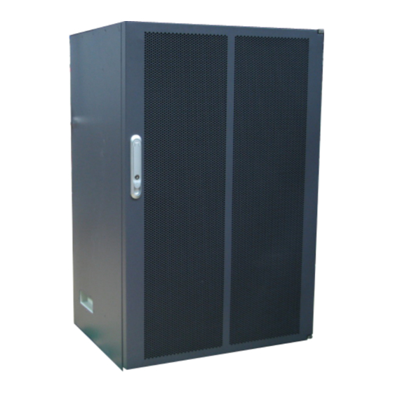
Figure 2-1 Exterior of a BTS3900 Cabinet
29
Figure 2-2 Dimensions of a BTS3900 Cabinet
30
3 BTS3900 Hardware Configuration
31
Board and Module Configurations
32
Module Configurations in the Cabinet
32
Figure 3-1 Module Configurations in the BTS3900 Cabinet (-48 V DC)
32
Figure 3-2 Module Configurations in the BTS3900 Cabinet (+24 V DC)
33
Figure 3-3 Module Configurations in the BTS3900 Cabinet (AC)
33
Table 3-1 Components in the Cabinet
34
Board Configurations of the BBU3900
35
Figure 3-4 Slots in the BBU3900
35
Figure 3-5 Typical Configuration of the BBU3900 in GO Mode
36
Table 3-2 Principles for Configuring the Boards in the BBU3900 in GO Mode
36
Table 3-3 Principles for Configuring the Boards in the BBU3900 in UO Mode
37
Figure 3-6 Typical Configuration of the BBU3900 in UO Mode
38
Table 3-4 Principles for Configuring the Boards in the BBU3900 in lo Mode
38
Figure 3-7 Typical Configuration of the BBU3900 in lo Mode
39
Table 3-5 Principles for Configuring the Boards in the BBU3900 in GU Mode
40
Figure 3-8 Typical Configuration of the BBU3900 in GU Mode
41
Table 3-6 Principles for Configuring the Boards in the BBU3900 in GL Mode
41
Figure 3-9 Typical Configuration of the BBU3900 in GL Mode
42
Table 3-7 Principles for Configuring the Boards in the BBU3900 in UL Mode
43
Combinations of Cabinets
44
Figure 3-10 Typical Configuration of the BBU3900 in UL Mode
44
Figure 3-11 Two BTS3900 (-48 V DC) Cabinets Installed Side by Side
45
Figure 3-12 Two BTS3900 (+24 V DC) Cabinets Installed Side by Side
45
Figure 3-13 Two BTS3900 (AC) Cabinets Installed Side by Side
46
Figure 3-14 Two Stacked BTS3900 (-48 V DC) Cabinets
47
Power System of the BTS3900
48
Figure 3-15 Two Stacked BTS3900 (AC) Cabinets
48
Table 3-8 Applicable AC Input Voltage Ranges
48
Configurations of the Upper-Level Circuit Breaker and Power Cables
49
Table 3-10 Recommended Configurations of the Upper-Level Circuit Breaker and Power Cables
49
Table 3-9 Applicable DC Input Voltage Ranges
49
Figure 3-16 Power Distribution of the BTS3900 (-48 V DC) Cabinet
50
Power Distribution of the BTS3900
50
Figure 3-17 Power Distribution of the BTS3900 (+24 V DC) Cabinet
51
Figure 3-18 Power Distribution of the BTS3900 (AC) Cabinet
51
Transmission Board Configurations
52
Table 3-11 Transmission Modes Supported by the Boards
52
CPRI Port Configurations
53
CPRI Port Specifications
53
Table 3-12 Specifications of the CPRI Ports on the Boards in the BBU
54
Table 3-13 Specifications of the CPRI Ports on the Rfus
54
Configuration Principles for the CPRI Ports on the RFU in the GSM Only Base Station
55
Figure 3-19 CPRI Port Connection Principles
55
Figure 3-20 Configuration Principles for the CPRI Ports in a Single Cabinet
56
Table 3-14 Configuration Principles for the CPRI Ports in a Single Cabinet
56
Configuration Principles for the CPRI Ports on the RFU in the UMTS Only Base Station
57
Figure 3-21 Configuration Principles for the CPRI Ports in Two Cabinets
57
Table 3-15 Configuration Principles for the CPRI Ports in Cabinet 1 of the Two Cabinets
57
Table 3-16 Configuration Principles for the CPRI Ports in Cabinet 2 of the Two Cabinets
57
Figure 3-22 CPRI Port Connection Principles
58
Configuration Principles for the CPRI Ports on the RFU in the LTE Only Base Station
59
Figure 3-25 CPRI Port Connection Principles
60
Configuration Principles for the CPRI Ports on the RFU in the GSM+UMTS Base Station
61
Figure 3-27 CPRI Port Connection Principles
61
Table 3-20 Configuration Principles for the CPRI Ports on the Mrfus (1)
62
Configuration Principles for the CPRI Ports on the RFU in the GSM+LTE Base Station
63
Table 3-21 Configuration Principles for the CPRI Ports on the Mrfus (2)
63
Figure 3-30 CPRI Port Connection Principles
64
Figure 3-31 Configuration Principles for the CPRI Ports on the Mrfus
64
Table 3-22 Configuration Principles for the CPRI Ports on the Mrfus
64
Configuration Principles for the CPRI Ports on the RFU in the UMTS+LTE Base Station
65
Figure 3-32 CPRI Port Configuration Principles
65
BTS3900 Monitoring System
66
BBU Monitoring Port
66
Table 3-23 CPRI Port Configuration Principles
66
Monitoring Principles of the Cabinet
67
Figure 3-33 Slot Assignment for the UPEU and UEIU
67
Table 3-24 Ports on the UPEU and UEIU
67
Figure 3-34 Monitoring System for the BTS3900 Cabinet (-48 V DC)
68
Figure 3-35 Monitoring System for the BTS3900 Cabinet (+24 V DC)
68
Customized Alarm Inputs
69
Figure 3-36 Monitoring System for the BTS3900 Cabinet (AC)
69
Table 3-25 Configuration of Monitoring Boards in the BTS3900
69
Figure 3-37 Customized Alarms Collected by the UPEU or UEIU
70
RF Configurations
71
Figure 3-38 Customized Alarms Collected by the EMU
71
RFU Configurations
72
Table 3-26 RFU Configurations
72
Slot Assignment for the Rfus in a Base Station Working in GSM Only Mode
73
Figure 3-39 GSM S4/4/4 (1G+1G+1G)
74
Figure 3-40 GSM S10/10/8 (2G+2G+2G)
74
Table 3-27 Slot Assignment for Grfus or Drfus
74
Figure 3-41 GSM S4/4/4 & S4/4/4 (1G+1G+1G & 1G+1G+1G)
75
Table 3-28 Slot Assignment for Grfus or Drfus
75
Table 3-29 Slot Assignment for Grfus or Drfus
75
Figure 3-42 GSM S8/8/8 & S8/8/8 (2G+2G+2G & 2G+2G+2G)
76
Slot Assignment for the Rfus in a Base Station Working in UMTS Only Mode
76
Figure 3-43 UMTS S1/1/1 (1W+1W+1W)
77
Figure 3-44 UMTS S4/4/4 (2W+2W+2W)
77
Slot Assignment for the Rfus in a Base Station Working in LTE Only Mode
77
Figure 3-45 LRFU 2T2R 3 X 20 Mhz
78
Table 3-30 Slot Assignment for Mrfus and Lrfus in a Single-Band Base Station
78
Figure 3-46 LRFU 4T4R 3 X 20 Mhz
79
Table 3-31 Slot Assignment for Mrfus and Lrfus in a Dual-Band Base Station
79
Figure 3-47 LRFU 3 X 20 Mhz+Mrfu 3 X 20 Mhz
80
Slot Assignment for the Rfus in a Base Station Working in GSM+UMTS Mode
80
Table 3-32 Slot Assignment for Grfus (or Drfus) and Wrfus
81
Figure 3-48 GSM 900M S4/4/4+UMTS 1800M S1/1/1
82
Table 3-33 Slot Assignment for Grfus (or Drfus) and Wrfus
82
Figure 3-49 GSM S4/4/4 & S4/4/4+UMTS 1800M S1/1/1
83
Table 3-34 RFU Slot Assignment for Mrfus
83
Figure 3-50 GSM S4/2/2 & S4/4/4+UMTS 900M S1/1/1
84
Table 3-35 RFU Slot Assignment for Grfus (or Drfus) and Mrfus
84
Table 3-36 RFU Slot Assignment for Mrfus, Grfus (or Drfus), and Wrfus
85
Figure 3-52 3MRFU+6GRFU+3WRFU
86
Slot Assignment for the Rfus in a Base Station Working in GSM+LTE Mode
86
Figure 3-53 MRFU900M 2T2R 3 X 20 Mhz+Mrfu1800M 2T2R 3 X 20 Mhz
87
Table 3-37 Slot Assignment for Mrfus in a Dual-Band Base Station
87
Figure 3-54 MRFU900M 2T2R 3 X 20 Mhz+6Grfu1800M
88
Table 3-38 Slot Assignment for Mrfus and Grfus in a Dual-Band Base Station
88
Table 3-39 Slot Assignment for Mrfus and Lrfus in a Dual-Band Base Station
88
Figure 3-55 3 X 20 Mhz 2T2R
89
Table 3-40 Slot Assignment for Drfus (or Grfus) and Lrfus in a Dual-Band Base Station
89
Figure 3-56 3GRFU+LRFU 3 X 20 Mhz
90
Table 3-41 Slot Assignment for Mrfus, Grfus, and Lrfus in a Tri-Band Base Station
90
Figure 3-57 MRFU900M 3 X 20 Mhz+3Grfu1800M+Lrfu 3 X 20 Mhz
91
Slot Assignment for the Rfus in a Base Station Working in UMTS+LTE Mode
91
Figure 3-58 UMTS S1/1/1+LTE 3 X 20 Mhz
92
Table 3-42 Slot Assignment for Wrfus and Lrfus
92
4 BTS3900 Components
93
BBU3900 Equipment
95
Exterior of the BBU3900
95
Figure 4-1 BBU3900
95
Boards and Module of the BBU3900
96
Figure 4-2 the Position of the ESN (1)
96
Figure 4-3 the Position of the ESN (2)
96
Figure 4-4 GTMU Panel
97
Figure 4-5 Gtmub Panel
97
Table 4-1 Leds on the GTMU
98
Table 4-2 Leds and Their Status
98
Table 4-3 Ports on the GTMU
99
Table 4-4 Details of the DIP Switch S1
100
Table 4-5 Details of the DIP Switch S2
101
Table 4-6 Details of the DIP Switch S4
101
Table 4-7 Details of the DIP Switch S5
101
Figure 4-6 Panel of the WMPT
102
Figure 4-7 Leds Beside the Three Ports on the WMPT
103
Table 4-8 Leds on the WMPT Panel
103
Table 4-9 Leds and Their Status
104
Table 4-10 Ports on the WMPT Panel
104
Figure 4-8 DIP Switches on the WMPT
105
Table 4-11 Settings of SW1
105
Figure 4-9 LMPT
106
Table 4-12 Settings of SW2
106
Table 4-13 Leds on the Panel of the LMPT
107
Table 4-14 Ports and Leds
108
Figure 4-10 Panel of the Wbbpa
109
Table 4-15 Ports on the Panel of the LMPT
109
Figure 4-11 Panel of the Wbbpb
110
Figure 4-12 Panel of the Wbbpd
110
Table 4-16 Specifications of the WBBP
110
Table 4-17 Leds on the WBBP and Their Status
111
Table 4-18 Leds Indicating the Status of the SFP Links
111
Figure 4-13 Panel of the Lbbpb
112
Figure 4-14 Panel of the Lbbpc
112
Table 4-19 Ports on the Panels of the Wbbpa and Wbbpb
112
Table 4-20 Ports on the Wbbpd
112
Table 4-21 Specifications of the LBBP
113
Table 4-22 Specifications of the LBBP
113
Table 4-23 Leds on the LBBP
114
Table 4-24 Leds Indicating the Status of the SFP Links
114
Table 4-25 Ports on the LBBP
115
Figure 4-15 FAN Panel
116
Figure 4-16 Fanc Panel
116
Figure 4-17 Upeua Panel
117
Table 4-26 LED on the FAN Panel
117
Figure 4-18 Upeub Panel
118
Figure 4-19 Upeuc Panel
118
Figure 4-20 Slots in the BBU
119
Table 4-27 LED on the Panel of the UPEU
119
Table 4-28 Description on the Ports
119
Figure 4-21 Panel of the UEIU
120
Figure 4-22 Panel of the Uscub1 (0.5 U)
121
Figure 4-23 Panel of the Uscub2 (1 U)
121
Table 4-29 Ports on the Panel of the UEIU
121
Table 4-30 Leds on the USCU
122
Table 4-31 Leds on the TOD Port
123
Table 4-32 Ports on the USCU
123
Figure 4-24 Panel of the UTRP2 Supporting Two Optical Ports
124
Figure 4-25 Panel of the UTRP3, UTRP4, and Utrpb4 Supporting Eight E1S/T1S
124
Figure 4-26 Panel of the UTRP6 Supporting One STM-1
124
Table 4-33 Specifications of the UTRP
124
Figure 4-27 Panel of the UTRP Supporting Four Electrical Ports
125
Table 4-34 Leds on the Panel of the UTRP
125
Table 4-35 Leds on the Ethernet Ports of the UTRP2 and UTRP9
126
Figure 4-28 DIP Switch on the UTRP3 or UTRP4
127
Table 4-36 Ports of the UTRP2 Supporting Two Optical Ports
127
Table 4-37 Ports on the Panel of the UTRP3, UTRP4 an Utrpb4 Supporting Eight E1S/T1S
127
Table 4-38 Port of the UTRP6 Supporting One STM-1
127
Table 4-39 Ports of the UTRP9 Supporting Four Electrical Ports
127
Figure 4-29 DIP Switch on the Utrpb4
128
Table 4-40 DIP Switch SW1 on the UTRP
128
Table 4-41 DIP Switch SW2 on the UTRP
128
Figure 4-30 Panel of the UBRI
129
Table 4-42 DIP Switch SW3 on the UTRP
129
Table 4-43 Leds on the Panel of the UBRI
130
Table 4-44 CPRI Link Status LED
130
Grfu
131
Figure 4-31 GRFU Panel
131
Table 4-45 Ports on the Panel of the UBRI
131
Figure 4-32 Logical Structure of the GRFU
132
Table 4-46 Leds on the GRFU Panel
133
Table 4-47 Ports on the GRFU Panel
134
Drfu
135
Figure 4-33 Panel of the DRFU of 900 Mhz
136
Figure 4-34 Panel of the DRFU of 1800 Mhz
137
Figure 4-35 Logical Structure of the DRFU
138
Table 4-48 Status of the Leds on the DRFU
139
Table 4-49 Ports and Sockets on the DRFU
140
Wrfu
141
Figure 4-36 Panel of the WRFU
141
Figure 4-37 Principle of the WRFU
142
Table 4-50 Leds on the MRFU Panel
143
Table 4-51 Ports on the WRFU Panel
144
Mrfu
145
Figure 4-38 Panel of the MRFU
145
Figure 4-39 Logical Structure of the MRFU
146
Table 4-52 Leds on the Panel of the MRFU
147
Table 4-53 Ports on the Panel of the MRFU
148
Lrfu
149
Figure 4-40 Panel of the LRFU
149
Figure 4-41 Logical Structure of the LRFU
150
Table 4-54 Leds on the LRFU
151
Dcdu-01
152
Table 4-55 Ports on the Panel of the LRFU
152
Figure 4-42 Panel of the DCDU-01
153
Table 4-56 Ports, Terminals, and Power Switches on the Panel of the DCDU-01
153
Fan Box
154
Figure 4-43 Fan Box
154
Figure 4-44 Ports on the FMU Board
154
Gatm
155
Figure 4-45 GATM Panel
155
Table 4-57 Leds on the FMU Board
155
Table 4-58 Ports on the FMU Board
155
Table 4-59 Leds on the GATM
156
Elu
157
Power Equipment (DC/DC)
157
Figure 4-46 ELU
157
Table 4-60 Ports and Socket on the GATM
157
Components of the Power Equipment (DC/DC)
158
Figure 4-47 Power Equipment (DC/DC)
158
Psu (DC/DC)
158
Table 4-61 Components of the Power Equipment (DC/DC)
158
Figure 4-48 Panel of the PSU (DC/DC)
159
Table 4-62 Leds on the Panel of the PSU (DC/DC)
159
Figure 4-49 Power Subrack (DC/DC)
160
Power Subrack (DC/DC)
160
Power Equipment (AC/DC)
161
Components of the Power Equipment (AC/DC)
161
Table 4-63 Ports and Terminals on the Power Subrack (DC/DC)
161
Pmu
162
Figure 4-50 Power Equipment (AC/DC)
162
Table 4-64 Components of the Power Equipment (AC/DC)
162
Figure 4-52 Front Panel of the PMU
163
Table 4-65 Ports and Switch on the PMU
163
Table 4-66 Leds on the Panel of the PMU
164
Psu (Ac/DC)
165
Figure 4-53 Right Panel of the PMU
165
Figure 4-54 Panel of the PSU (AC/DC)
166
Table 4-67 Leds on the Panel of the PSU (AC/DC)
166
Power Subrack (AC/DC)
167
Figure 4-55 Panel of the Power Subrack (AC/DC)
168
Table 4-68 Terminals and Switch on the Power Subrack (AC/DC)
168
5 BTS3900 Cables
169
List of BTS3900 Cables
171
Table 5-1 Power Cables and PGND Cables
171
Table 5-2 Transmission Cables
173
Table 5-3 CPRI Cables
174
Table 5-4 Signal Cables
175
BTS3900 Cable Connections
176
Table 5-5 RF Cables
176
Power Cable Connections
177
Table 5-6 Power Cables of the BTS3900 (-48 V)
178
Table 5-7 Power Cables of the BTS3900 (+24 V)
178
Figure 5-3 Power Cable Connections of the BTS3900 (220 V)
179
Table 5-8 Power Cables of the BTS3900 (220 V)
179
Figure 5-4 E1/T1 Cable Connections
180
Figure 5-5 E1/T1 Cable Connections
180
Table 5-9 E1/T1 Cable Connections
180
Transmission Cable Connections
180
Figure 5-6 FE/GE Ethernet Cable Connections
181
Figure 5-7 FE/GE Optical Cable Connections
181
Table 5-10 E1/T1 Cable Connections
181
Table 5-11 FE/GE Ethernet Cable Connections
181
Table 5-12 FE/GE Optical Cable Connections
181
Figure 5-8 E1/T1 Cable Connections (1)
182
Figure 5-9 E1/T1 Cable Connections (2)
182
Table 5-13 E1/T1 Cable Connections (1)
182
Table 5-14 E1/T1 Cable Connections (2)
182
Figure 5-10 FE/GE Ethernet Cable Connections (1)
183
Figure 5-11 FE/GE Ethernet Cable Connections (2)
183
Figure 5-12 FE/GE Optical Cable Connections (1)
183
Table 5-15 FE/GE Ethernet Cable Connections (1)
183
Table 5-16 FE/GE Ethernet Cable Connections (2)
183
Figure 5-13 FE/GE Optical Cable Connections (2)
184
Figure 5-14 E1/T1 Cable Connections
184
Table 5-17 FE/GE Optical Cable Connections (1)
184
Table 5-18 FE/GE Optical Cable Connections (2)
184
Figure 5-15 FE/GE Optical Cable Connections
185
Figure 5-16 Transmission Cable Connection for a GSM+UMTS Base Station in TDM Common Transmission Mode
185
Table 5-19 E1/T1 Cable Connections
185
Table 5-20 FE/GE Optical Cable Connections
185
Figure 5-17 Transmission Cable Connection for a GSM+UMTS Base Station in TDM Common Transmission Mode
186
Figure 5-20 Transmission Cable Connections for a GSM+UMTS Base Station in IP over FE Common Transmission
187
Table 5-23 Transmission Cables for a GSM+UMTS Base Station in IP over E1 Common Transmission Mode
187
Table 5-24 Transmission Cables for a GSM+UMTS Base Station in IP over E1 Common Transmission Mode
187
Figure 5-21 Transmission Cable Connections for a GSM+UMTS Base Station in IP over FE Common Transmission
188
Table 5-25 Transmission Cable Connections for a GSM+UMTS Base Station in IP over FE Common Transmission
188
Table 5-26 Transmission Cable Connections for a GSM+UMTS Base Station in IP over FE Common Transmission
188
Figure 5-22 Transmission Cable Connections with FE Optical Ports for Interconnection and FE Electrical Ports
189
Figure 5-23 Transmission Cable Connections with FE Electrical Ports for Interconnection and FE Optical Ports
189
Table 5-27 Transmission Cables with FE Optical Ports for Interconnection and FE Electrical Ports Connected to the
189
Figure 5-24 E1/T1 Cable Connections in Separate Transmission Mode
190
Figure 5-25 FE/GE Cable Connections in Separate Transmission Mode (1)
190
Table 5-28 Transmission Cables with FE Electrical Ports for Interconnection and FE Optical Ports Connected to the
190
Table 5-29 E1/T1 Cable Connections in Separate Transmission Mode
190
Figure 5-26 FE/GE Cable Connections in Separate Transmission Mode (2)
191
Figure 5-27 Transmission Cable Connections for a GSM+LTE Base Station in IP over E1 Common Transmission
191
Table 5-30 FE/GE Cable Connections in Separate Transmission Mode (1)
191
Table 5-31 FE/GE Cable Connections in Separate Transmission Mode (2)
191
Figure 5-28 Transmission Cable Connections for a GSM+LTE Base Station in IP over E1 Common Transmission
192
Figure 5-29 Transmission Cable Connections for a GSM+LTE Base Station in IP over FE/GE Common Transmission
192
Table 5-32 Transmission Cables for a GSM+LTE Base Station in IP over E1 Common Transmission Mode
192
Table 5-33 Transmission Cables for a GSM+LTE Base Station in IP over E1 Common Transmission Mode
192
Figure 5-30 Transmission Cable Connections for a GSM+LTE Base Station in IP over FE/GE Common Transmission
193
Table 5-34 Transmission Cables for a GSM+LTE Base Station in IP over FE/GE Common Transmission Mode
193
Table 5-35 Transmission Cables for a GSM+LTE Base Station in IP over FE/GE Common Transmission Mode
193
Figure 5-31 Transmission Cable Connections with FE Electrical Ports for Interconnection and FE Optical Ports
194
Figure 5-32 Transmission Cable Connections with FE Optical Ports for Interconnection and FE Electrical Ports
194
Table 5-36 Transmission Cables with FE Electrical Ports for Interconnection and FE Optical Ports Connected to the
194
Figure 5-33 Transmission Cable Connections in a Base Station in GSM 4E1/T1+LTE FE/GE Mode (1)
195
Table 5-37 Transmission Cables with FE Optical Ports for Interconnection and FE Electrical Ports Connected to the
195
Table 5-38 Transmission Cable Connections in a Base Station in GSM 4E1/T1+LTE FE/GE Mode (1)
195
Figure 5-34 Transmission Cable Connections in a Base Station in GSM 4E1/T1+LTE FE/GE Mode (2)
196
Figure 5-35 Transmission Cable Connections in a Base Station in GSM 8E1/T1+LTE FE/GE Mode (1)
196
Table 5-39 Transmission Cable Connections in a Base Station in GSM 4E1/T1+LTE FE/GE Mode (2)
196
Table 5-40 Transmission Cable Connections in a Base Station in GSM 8E1/T1+LTE FE/GE Mode (1)
196
Figure 5-37 Transmission Cable Connections in a Base Station in GSM FE/GE+LTE FE/GE Mode (1)
197
Table 5-41 Transmission Cable Connections in a Base Station in GSM 8E1/T1+LTE FE/GE Mode (2)
197
Table 5-42 Transmission Cable Connections in a Base Station in GSM FE/GE+LTE FE/GE Mode (1)
197
Table 5-44 Transmission Cables for a UMTS+LTE Base Station in IP over E1 Common Transmission Mode
198
Figure 5-41 Transmission Cable Connections for a UMTS+LTE Base Station in IP over FE/GE Common
199
Table 5-45 Transmission Cables for a UMTS+LTE Base Station in IP over E1 Common Transmission Mode
199
Figure 5-42 Transmission Cable Connections for a UMTS+LTE Base Station in IP over FE/GE Common
200
Table 5-46 Transmission Cables for a UMTS+LTE Base Station in IP over FE/GE Common Transmission Mode
200
Table 5-47 Transmission Cables for a UMTS+LTE Base Station in IP over FE/GE Common Transmission Mode
200
Figure 5-43 Transmission Cable Connections for a UMTS+LTE Base Station in Route Backup Mode with IP Common
201
Figure 5-44 Transmission Cable Connections for a UMTS+LTE Base Station in Route Backup Mode with IP Common
201
Table 5-48 Transmission Cables for a UMTS+LTE Base Station in Route Backup Mode with IP Common Transmission
201
Figure 5-45 Transmission Cable Connections in Hybrid Transmission Mode (1)
202
Table 5-49 Transmission Cables for a UMTS+LTE Base Station in Route Backup Mode with IP Common Transmission
202
Table 5-50 Transmission Cables in Hybrid Transmission Mode (1)
202
Figure 5-46 Transmission Cable Connections in Hybrid Transmission Mode (2)
203
Table 5-51 Transmission Cables in Hybrid Transmission Mode (2)
203
CPRI Cable Connections
206
Figure 5-53 Star Topology
207
Figure 5-54 Chain Topology
207
Figure 5-55 Star Topology over CPRI Ports
208
Figure 5-56 Chain Topology over CPRI Ports
208
Figure 5-57 Chain Topology over CPRI Ports on the Wbbpd
209
Figure 5-58 CPRI Cable Connections in the 3 X 10 Mhz 2T2R Configuration
209
Figure 5-59 CPRI Cable Connections in the 3 X 20 Mhz 2T2R Configuration
210
Figure 5-60 CPRI Cable Connections in the 3 X 10 Mhz 4T4R Configuration
210
Figure 5-61 CPRI Cable Connections in the 3 X 20 Mhz 4T4R Configuration
211
Figure 5-62 Dual-Star Topology over CPRI Ports (1)
211
Figure 5-63 Dual-Star Topology over CPRI Ports (2)
212
Figure 5-64 Dual-Star Topology over CPRI Ports (3)
212
Figure 5-65 Dual-Star Topology over CPRI Ports (4)
212
Figure 5-67 CPRI Cable Connections in a Co-Cabinet Base Station with Wrfus and Drfus/Grfus (2)
214
Figure 5-68 CPRI Cable Connections in a Co-Cabinet Base Station with Mrfus and Wrfus (1)
215
Figure 5-69 CPRI Cable Connections in a Co-Cabinet Base Station with Mrfus and Wrfus (2)
215
Figure 5-70 CPRI Cable Connections in a Co-Cabinet Base Station with Mrfus and Drfus/Grfus
216
Figure 5-71 Dual-Star Topology over CPRI Ports
217
Figure 5-72 CPRI Cable Connections in Co-Cabinet Mode
217
Figure 5-73 CPRI Port Connection Principles
218
Monitoring Signal Cable Connections
218
Figure 5-74 Monitoring Signal Cable Connections of the BTS3900 (-48 V DC)
219
Table 5-58 Monitoring Signal Cable Connections of the BTS3900 (-48 V DC)
219
Figure 5-75 Monitoring Signal Cable Connections of the BTS3900 (+24 V DC)
220
Table 5-59 Monitoring Signal Cable Connections of the BTS3900 (+24 V DC)
220
Figure 5-76 Signal Cable Connections of the BTS3900 (AC)
221
RF Cable Connections
221
Table 5-60 Signal Cable Connections of the BTS3900 (AC)
221
Figure 5-77 Cable Connections in 1T2R Mode (1)
222
Figure 5-78 Cable Connections in 1T2R Mode (2)
223
Figure 5-79 Cable Connections with Three Carriers
224
Figure 5-80 Cable Connections with Nine Carriers
225
Figure 5-81 Cable Connections with 14 Carriers
226
Figure 5-82 Cable Connections with 24 Carriers
227
Figure 5-83 Cable Connections in 1T2R Mode (1)
228
Figure 5-84 Cable Connections in 1T2R Mode (2)
229
Figure 5-85 Cable Connections in 2T4R Mode
230
Figure 5-86 RF Cable Connections in 2T2R Mode
231
Figure 5-87 RF Cable Connections in 4T4R Mode
232
Figure 5-88 Cable Connections in G3U1 Mode
233
PGND Cables
234
Figure 5-89 Cable Connections in G9U1 Mode
234
Equipotential Cable
235
Figure 5-90 PGND Cable for the Cabinet
235
Figure 5-91 PGND Cable for the Modules
235
Figure 5-92 Equipotential Cable
235
BTS3900 Power Cable
236
Input Power Cable for the Cabinet
236
Figure 5-93 -48 V Power Cable
236
Table 5-61 -48 V Power Cable
236
Figure 5-94 +24 V Power Cable
237
Table 5-62 +24 V Power Cable
237
Power Cable for the DCDU-01
238
Figure 5-95 AC Power Cable (220 V AC, Single-Phase)
238
Table 5-63 220 V Power Cable
238
Power Cable for the BBU
239
Figure 5-96 Power Cable for the DCDU-01
239
Figure 5-97 Power Cable for the BBU
239
Table 5-64 Power Cable for the DCDU-01
239
Power Cable for the Fan Box
240
Power Cable for the RFU
240
Figure 5-98 Power Cable for the Fan Box
240
Table 5-65 Pin Assignment of the Power Cable for the BBU
240
Table 5-66 Pin Assignment for the Wires of the Power Cable for the Fan Box
240
Power Cable for the GATM
241
Figure 5-99 Power Cable for the RFU
241
Table 5-67 Pin Assignment for the Wires of the Power Cable for the RFU
241
BTS3900 Transmission Cable
242
Figure 5-100 Power Cable for the GATM
242
Table 5-68 Pin Assignment for the Wires of the Power Cable for the GATM
242
E1/T1 Cable
243
Figure 5-101 E1/T1 Cable
243
Table 5-69 Connectors of the 75-Ohm E1 Coaxial Cable
243
Table 5-70 Pin Assignment for the Wires of the 75-Ohm E1 Coaxial Cable
244
Table 5-71 Pin Assignment for the Wires of the 120-Ohm E1 Twisted Pair Cable
244
FE/GE Cable
245
Figure 5-102 FE/GE Cable
245
FE/GE Optical Cable
246
Figure 5-103 FE/GE Optical Cable (FC and LC Connectors)
246
Figure 5-104 FE/GE Optical Cable (SC and LC Connectors)
246
Table 5-72 Pin Assignment for the Wires of the FE/GE Cable
246
Cable between Two FE Electrical Ports
247
Cable between Two FE Optical Ports
247
Figure 5-105 FE/GE Optical Cable (LC and LC Connectors)
247
Figure 5-106 Cable between Two FE Electrical Ports
247
CPRI Electrical Cable
248
BTS3900 Signal Cable
248
Figure 5-107 Cable between Two FE Optical Ports
248
Figure 5-108 CPRI Electrical Cable
248
Figure 5-109 Monitoring Signal Cable for the PMU
249
Monitoring Signal Cable for the PMU
249
Table 5-73 Pin Assignment for the Wires of the Monitoring Signal Cable for the PMU
249
Figure 5-110 Monitoring Signal Cable for the PSU (DC/DC)
250
In-Position Signal Cable for the PSU (DC/DC)
250
Monitoring Signal Cable for the PSU (DC/DC)
250
Figure 5-111 In-Position Signal Cable for the PSU (DC/DC)
251
Monitoring Signal Cable for the Fan Box
251
Table 5-74 Pin Assignment for the Wires of the In-Position Signal Cable for the PSU (DC/DC)
251
Fan Box Cascade Signal Cable
252
Figure 5-112 Monitoring Signal Cable for the Fan Box
252
Table 5-75 Pin Assignment for the Wires of the Monitoring Signal Cable for the Fan Box
252
Figure 5-113 Fan Box Cascade Signal Cable
253
Monitoring Signal Cable for the EMU
253
Table 5-76 Pin Assignment of the Fan Box Cascade Signal Cable
253
Figure 5-114 Monitoring Signal Cable for the EMU
254
Monitoring Signal Cable for the GATM
254
Table 5-77 Pin Assignment for the Wires of the Monitoring Signal Cable for the EMU
254
BBU Alarm Cable
255
Figure 5-115 Monitoring Signal Cable for the GATM
255
Table 5-78 Pin Assignment for the Wires of the Monitoring Signal Cable for the GATM
255
Figure 5-116 BBU Alarm Cable
256
Table 5-79 Pin Assignment for the Wires of the BBU Alarm Cable
256
Figure 5-117 GPS Clock Signal Cable
257
GPS Clock Signal Cable
257
Signal Cable for the ELU
258
BTS3900 RF Cable
258
Figure 5-118 Signal Cable for the ELU
258
Table 5-80 Pin Assignment for the Wires of the Signal Cable for the ELU
258
Figure 5-119 RF Jumper
259
Figure 5-120 Inter-RFU RF Signal Cable
259
Inter-RFU RF Signal Cable
259
RF Jumper
259
6 BTS3900 Auxiliary Equipment
261
PS4890 Cabinet
262
Figure 6-1 Cable Connections between the BTS3900 and the PS4890
262
Table 6-1 Cables between the BTS3900 and the PS4890
262
Emu
263
Ddf
263
Figure 6-2 Structure of the DDF
263
Table 6-2 Technical Specifications of the DDF
264
Advertisement
Advertisement
Related Products
Huawei BTS3900A
Huawei BTS3900L GSM
Huawei BTS3900L LTE
Huawei BTS3900L WCDMA
Huawei BTS3900 GSM
Huawei BTS3900 V200R010
Huawei BTS3900 V200R011
Huawei BTS3902E WCDMA
Huawei BTS3900 LTE
Huawei BTS3900B GSM
Huawei Categories
Cell Phone
Network Router
Wireless Router
Modem
Inverter
More Huawei Manuals
Login
Sign In
OR
Sign in with Facebook
Sign in with Google
Upload manual
Upload from disk
Upload from URL