Sign In
Upload
Manuals
Brands
HP Manuals
Server
rp7405
HP rp7405 PA-RISC Servers Manuals
Manuals and User Guides for HP rp7405 PA-RISC Servers. We have
11
HP rp7405 PA-RISC Servers manuals available for free PDF download: Administrator's Manual, User Manual, Manual, Programmer's Manual, Configuration, Release Note, Limited Warranty
HP rp7405 Administrator's Manual (266 pages)
Server Software
Brand:
HP
| Category:
Software
| Size: 2.25 MB
Table of Contents
Table of Contents
3
Table of Contents
7
List of Figures
8
About this Document
11
New and Changed Information in this Edition
11
Document Organization
11
Typographic Conventions
12
Related Information
13
Publishing History
13
HP Encourages Your Comments
13
1 Getting Started with Npartitions
15
Introduction to Npartitions
15
Operating Systems Supported on Npartitions
15
Npartition Operating System Support
15
HP Server Support for Npartitions
16
HP Superdome Hybrid Servers: Intel® Itanium® 2 and PA-RISC Npartition Mixing
17
HP Servers Supporting Npartitions
17
Hardware Components of Npartition-Capable Servers
18
Administration Tools for Npartitions
18
Commands for Configuring Npartitions
19
Npartition Commands Releases
20
Npartition Commands Descriptions
20
Availability of Npartition Commands
21
Enhanced Npartitions Commands for Windows
21
Enhanced Npartition Commands for Linux
22
Partition Manager
22
Partition Manager Version 2.0 for Windows
23
Npartition Properties
23
Assigned and Unassigned Cells
24
Base Cells
24
Core Cells
24
Partition Numbers
24
Active and Inactive Cells
25
Cell Local Memory
25
Cell Property Details
25
Active and Inactive Npartition Boot States
27
Overview of Managing Npartitions
27
Basics of Listing Npartition and Complex Status
27
Basics of Npartition Creation
29
Basics of Npartition Modification
30
Genesis Partition
30
Npartition Modification Tasks
31
Basics of Npartition Booting and Resetting
32
Boot Process for Cells and Npartitions
32
Common Npartition Boot Commands and Tasks
33
Complex Profile
36
Changing the Server Complex Profile
37
How the Complex Profile Is Updated
37
Complex Profile Entry Locking and Unlocking
38
Complex Profile Group Details
39
Complex Profile Group Details
40
Remote and Local Management of Npartitions
41
Intelligent Platform Management Interface (IPMI)
41
IPMI Block Transfer (IPMI BT)
42
IPMI over LAN
42
Npartition Configuration Privilege
42
Local Management
43
Web-Based Enterprise Management (WBEM)
43
Remote Management Using WBEM
44
WBEM Remote Management Files
44
Npartition Commands Support for Remote Management Using WBEM
45
Partition Manager Support for Remote Management Using WBEM
45
Npartition Commands Support for Remote Management Using IPMI over LAN
46
Remote Management Using IPMI over LAN
46
Partition Manager Version 2.0 Switch Complexes Dialog
46
Partition Manager Support for Remote Management Using IPMI over LAN
47
Licensing Information: Getting Server Product Details
47
Npartition and Virtual Partition Unique Identifiers
47
Unique Ids for an Npartition and Complex
48
Unique Ids for Virtual Partitions (Vpars)
48
2 Npartition Server Hardware Overview
49
Sx1000 Chipset for HP Servers
49
Sx2000 Chipset for HP Servers
49
Model Identifiers for Machine Hardware
49
Server Hardware Details: Cell-Based HP Servers
51
Models of Cell-Based HP Servers
51
Two-Cell Npartition Server Model
55
Two-Cell HP Server Cabinet
55
Four-Cell Npartition Server Model
56
Four-Cell HP Server Cabinet
56
Superdome Server Models
57
HP Superdome Server Cabinet
57
HP Superdome 16-/32-Way Servers: SD16000, SD16A, and SD16B
58
HP Superdome 32-/64-Way Servers: SD32000, SD32A, and SD32B
58
HP Superdome 64-/128-Way Servers: SD64000, SD64A, and SD64B
59
HP Superdome I/O Expansion Cabinet
59
3 Planning Npartitions
61
Npartition Hardware Requirements for Operating Systems
61
Operating System Hardware Requirements
61
Configuration Requirements for Npartitions
62
Recommended Npartition Configurations
63
Recommended HP Superdome Npartition Configurations
64
4 Using Management Interfaces and Tools
67
SMS (Support Management Station) for HP Superdome Servers
67
Overview of Npartition Service Processor (MP or GSP) Interfaces
67
Service Processor (MP or GSP) Features
68
Service Processor Accounts and Access Levels
69
Npartition Console Features
70
Npartition Console Access Versus Direct os Login
71
Boot Console Handler System Boot Environment
71
Extensible Firmware Interface System Boot Environment
72
Windows Special Administration Console (SAC)
72
Windows SAC Commands
73
Accessing and Using the Service Processor
74
Overview of a Service Processor Login Session
75
Using Service Processor Menus
76
Navigating through Service Processor Menus
76
Network Configuration for a Service Processor
77
Viewing Console Logs
77
Viewing Chassis Codes or Event Logs
78
Virtual Front Panel (VFP) Npartition Views
79
Command Reference for Service Processor Commands
80
Service Processor (MP or GSP) Command Reference
80
Command Reference for EFI Shell Commands
81
EFI Shell Command Reference
81
Command Reference for BCH Menu Commands
84
Boot Console Handler (BCH) Command Reference
84
5 Booting and Resetting Npartitions
87
Overview of Npartition System Booting
87
Boot Process Differences for Npartitions on HP 9000 Servers and HP Integrity Servers
88
Types of Booting and Resetting for Npartitions
89
System Boot Configuration Options
91
HP 9000 Boot Configuration Options
91
HP Integrity Boot Configuration Options
91
Tools for Booting Npartitions
95
Task Summaries for Npartition Boot and Reset
96
Npartition Boot and Reset Task Summaries
96
Troubleshooting Boot Problems
100
Accessing Npartition Console and System Boot Interfaces
101
Monitoring Npartition Boot Activity
104
Finding Bootable Devices
106
Performing a Transfer of Control Reset
107
Booting and Shutting down HP-UX
108
HP-UX Support for Cell Local Memory
108
Adding HP-UX to the Boot Options List
109
Booting HP-UX
110
HP-UX Booting
110
Single-User Mode HP-UX Booting
114
Single-User HP-UX Boot
115
LVM-Maintenance Mode HP-UX Booting
116
Shutting down HP-UX
117
Booting and Shutting down HP Openvms I64
119
Adding HP Openvms to the Boot Options List
120
HP Openvms I64 Support for Cell Local Memory
120
Booting HP Openvms
122
Shutting down HP Openvms
123
Booting and Shutting down Microsoft Windows
124
Microsoft Windows Support for Cell Local Memory
124
Adding Microsoft Windows to the Boot Options List
125
Booting Microsoft Windows
126
Shutting down Microsoft Windows
128
Booting and Shutting down Linux
129
Linux Support for Cell Local Memory
129
Adding Linux to the Boot Options List
130
Booting Red hat Enterprise Linux
131
Booting Suse Linux Enterprise Server
132
Shutting down Linux
134
Rebooting and Resetting Npartitions
135
Performing a Reboot for Reconfig
139
Shutting down to a Shutdown for Reconfig (Inactive) State
141
Booting an Inactive Npartition
146
Booting over a Network
147
Booting to the HP-UX Initial System Loader (ISL)
149
Booting to the HP-UX Loader (HPUX.EFI)
150
Using HP-UX Loader Commands
151
HPUX Boot Loader Commands Issued from ISL
151
HPUX.EFI Boot Loader Commands
151
Booting to the Linux Loader (ELILO.EFI)
152
Linux Boot Option Management
153
Linux Loader Configuration File (Elilo.conf)
153
Using Linux Loader (ELILO) Commands
154
Configuring Boot Paths and Options
155
Configuring Autoboot Options
158
Configuring Boot-Time System Tests
161
6 Creating and Configuring Npartitions
165
Tools for Configuring Npartitions
165
Task Summaries for Creating and Configuring Npartitions
165
Npartition Configuration Task Summaries
166
Creating a Genesis Partition
170
Creating a New Npartition
172
Removing (Deleting) an Npartition
176
Assigning (Adding) Cells to an Npartition
179
Unassigning (Removing) Cells from an Npartition
182
Renaming an Npartition
185
Renaming a Server Complex
187
Setting Cell Attributes
189
Setting Npartition Core Cell Choices
194
Unlocking Complex Profile Entries
198
Canceling Pending Changes to the Complex Profile
199
7 Managing Hardware Resources
201
Tools for Managing Hardware
201
Task Summaries for Hardware Resource Management
201
Hardware Management Task Summaries
202
Powering Server Cabinets on and off
205
Powering Cells and I/O Chassis on and off
206
Turning Attention Indicators (Leds) on and off
209
Attention Indicator (LED) States and Meanings
209
Turning Attention Indicators on and off
212
Configuring and Deconfiguring Cells
213
Configuring and Deconfiguring Processors
217
Enabling and Disabling Hyper-Threading on Dual-Core Intel® Itanium® 2 Processors
218
Checking the Hyper-Threading Status for an Npartition
219
Configuring and Deconfiguring Memory (Dimms)
220
Enabling Hyper-Threading for an Npartition
220
Complex Health Analysis of a Server
222
8 Listing Npartition and Hardware Status
223
Tools for Listing Status
223
Task Summaries for Npartition and Hardware Status
223
Hardware and Npartition Status Task Summaries
224
Listing Cell Configurations
226
Listing Processor Configurations
227
Listing Memory Configurations
229
Listing Input/Output (I/O) Configurations
231
Listing Cabinets in a Server Complex
234
Listing Product and Serial Numbers
235
Listing Npartition Configurations
236
Listing the Local Npartition Number
237
Listing Power Status and Power Supplies
238
Listing Fan and Blower Status
240
A Npartition Commands
243
Specifying Cells and I/O Chassis to Commands
243
Cell Specification Formats
243
Cell Ids in Global Cell Number Format
243
I/O Specification Format
244
Cell Ids in Hardware Location Format
244
Specifying Remote Management Options to Commands
247
A-1 I/O Specification Formats for Cabinets, Bays, and Chassis
247
Parcreate Command
249
Parmodify Command
252
Parremove Command
256
Parstatus Command
258
Parunlock Command
260
Fruled Command
262
Frupower Command
264
Cplxmodify Command
266
Advertisement
HP rp7405 User Manual (146 pages)
HP RP7405/7410 Servers User Guide
Brand:
HP
| Category:
Server
| Size: 2.77 MB
Table of Contents
User Guide
1
Legal Notices
2
Table of Contents
3
Revision History
12
Table 1 Revisions
12
Notational Conventions
13
Safety and Regulatory
14
Figure 1 Declaration of Conformity
15
Usa Radio Frequency Interference Fcc Notice
16
Figure 2 Japanese RFI
16
Canada Rfi Statement
17
European Union Rfi Statement
17
Figure 3 Korean RFI
17
Figure 4 Taiwan Area EMC
18
Installation Conditions
19
Lithium Battery Caution
20
Figure 5 C-Tick Label
20
Laser Safety
21
1 Introduction
23
Hp Rp7405/Rp7410 Overview
24
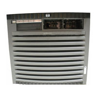
Figure 1-1 Hp Rp7405/Rp7410 Server (Front View)
24
Cell Board
25
Figure 1-2 Hp Rp7405/Rp7410 Server (Without Front Bezel)
25
I/O Subsystem
26
System Backplane
26
Hp Rp7405 Servers
27
Table 1-1. Hp Rp7405 Servers
27
Table 1-2. Hp Rp7405-To-Rp7410 Upgrades
27
Detailed Hp Rp7405/Rp7410 Description
28
Figure 1-3 Hp Rp7410 8-Way Block Diagram
28
Cell Board
29
Figure 1-4 Cell Controller
29
Figure 1-5 Cell Board
29
Figure 1-6 Memory Subsystem
30
Cells and Npartitions
31
Table 1-3 Hp Rp7405/Rp7410 Dimms
31
Figure 1-7 Internal Disks
32
Figure 1-8 System Backplane Block Diagram
33
I/O Subsystem
33
System Backplane
33
Figure 1-9 I/O Subsystem Architecture
34
Table 1-4 PCI Slot Types
35
Package Description
36
Figure 1-10 Right-Front View of Hp Rp7405/Rp7410
37
Figure 1-11 Left-Rear View of Hp Rp7405/Rp7410
38
2 Installation
39
Unpacking the Server
40
Unpacking a Racked Server
40
Figure 2-1 Removing the Polystraps and Cardboard
41
Figure 2-2 Removing the Shipping Bolts and Plastic Cover
42
Figure 2-3 Preparing to Roll off the Pallet
43
Unpacking a Non-Racked Server
44
Figure 2-4. Securing the Cabinet
44
Figure 2-5 RONI Lifter
45
Figure 2-6 Server with Shipping Box Removed
45
Figure 2-7 Remove Cushions for Lift Access
46
Figure 2-8 Raising a Server off the Pallet
47
Figure 2-9 Lifting the Server to the Rack
47
Figure 2-10 Positioning the Lift Handles
48
Figure 2-11 Inserting the Pins into the Rack
49
Figure 2-12 Lift Handles Mounted
49
Installing Server into the Rack
50
Figure 2-13 Lifting the Server
50
Installing the Cable Management Arm (CMA)
51
Figure 2-14 Cable Management Arm
51
Figure 2-15 Attaching CMA to Rack
51
Installing Add-On Products
52
Figure 2-16 Attaching CMA to the Server
52
Figure 2-17 Embedded Disks
53
Table 2-1. Hp Rp7405/Rp7410 Dimms
54
Figure 2-18. Cell Board (Two Processors and CC Shown)
54
Figure 2-19 DIMM Loading Sequence
55
Connecting AC Input Power
56
Figure 2-20 Power Cord Configuration
56
Figure 2-21. Power Source Vs. Power Distribution
57
MP Core I/O Connections
58
MP/SCSI Connections
58
LAN/SCSI Connections
58
Management Processor Access
58
Setting up the CE Tool (PC)
59
Standby Power and Logging in to the MP
60
Figure 2-22 Front Panel Display
61
Configuring LAN Information for the MP
62
Figure 2-23 MP Main Menu
62
Figure 2-24 the Lc Command Screen
63
Verifying Presence of the Cell Boards
64
Figure 2-25 the Ls Command Screen
64
Figure 2-26 the du Command Screen
65
Powering on the Hp Rp7405/Rp7410 Server
66
Selecting a Boot Partition Using the Management Processor
67
Verifying the System Configuration Using Boot Console Handler (BCH)
68
Booting HP-UX Using Boot Console Handler (BCH)
69
3 Troubleshooting
71
Common Installation Problems
72
The Server Does Not Power on
73
The Server Powers on but then Shuts down with a Fault Light
73
Hp Rp7405/Rp7410 LED Indicators
73
Table 3-1. Front Panel Leds
73
Table 3-2 BPS Leds
74
Table 3-3. PCI Power Supply Leds
74
Table 3-4. System, Standby, and I/O Fan Leds
75
Table 3-5. SINC POST Leds
75
Table 3-6 OL* Leds
76
Table 3-7. OL* Leds States
76
Table 3-8. MP Core I/O Leds
76
Table 3-9. LAN/SCSI Leds
77
4 Removal and Replacement
79
Shutting down Npartitions and Powering off Hardware Components
80
Shutting down an Npartition
80
Powering off Hardware Components
81
Removing and Replacing the Top Cover
83
Figure 4-1 Top Cover
83
Figure 4-2 Top Cover Retaining Screws
84
Removing the Top Cover
84
Replacing the Top Cover
84
Removing and Replacing a Disk Drive
85
Figure 4-3 Disk Drive Location
85
Figure 4-4 Disk Drive Detail
86
Removing a Disk Drive
86
Replacing a Disk Drive
86
Removing and Replacing a CD/DVD Drive
88
Figure 4-5 CD/DVD Location
88
Figure 4-6 CD/DVD Detail
89
Removing a CD/DVD Drive
89
Figure 4-7 CD/DVD Detail
90
Replacing a CD/DVD
90
Removing and Replacing a Front Smart Fan Assembly
91
Figure 4-8 Front Smart Fan Assembly Locations
91
Table 4-1 Front Smart Fan Assembly LED Indications
91
Figure 4-9 Front Fan Detail
92
Removing a Front Smart Fan Assembly
92
Replacing a Front Smart Fan Assembly
92
Removing and Replacing a Rear Smart Fan Assembly
93
Figure 4-10 Rear Smart Fan Assembly Locations
93
Table 4-2 Rear Smart Fan Assembly LED Indications
93
Figure 4-11 Rear Fan Detail
94
Removing a Rear Smart Fan Assembly
94
Replacing a Rear Smart Fan Assembly
94
Removing and Replacing a PCI Smart Fan Assembly
95
Figure 4-12 PCI Smart Fan Assembly Location
95
Table 4-3 Smart Fan Assembly LED Indications
95
Figure 4-13 PCI Smart Fan Assembly Detail
96
Removing a PCI Smart Fan Assembly
96
Replacing a PCI Smart Fan Assembly
96
Removing and Replacing a Bulk Power Supply
97
Figure 4-14 BPS Location
97
Figure 4-15 BPS Detail
98
Removing a BPS
98
Replacing a BPS
98
Removing and Replacing a PCI Power Module (Brick)
99
Figure 4-16. PCI Power Module Location
99
Table 4-4. PCI Power Module LED Indications
99
Figure 4-17 PCI Power Module Detail
100
Removing a PCI Power Module (Brick)
100
Replacing a PCI Power Module (Brick)
100
Removing and Replacing the PCI Voltage Regulator Modules
101
Removing PCI VRM
101
Replacing the PCI VRM
101
Figure 4-18 Locating the Vrms on PCI Backplane
101
Removing and Replacing a PCI Card
103
Figure 4-19 PCI Cards
103
Figure 4-20PCI Gate Detail
104
Removing and Replacing the Mass Storage Backplane
106
Removing the Backplane
106
Figure 4-21Locating Internal Disks
106
Figure 4-22Locating the Mass Storage Backplane
107
Figure 4-23Mass Storage Backplane
107
Replacing the Backplane
108
Removing and Replacing a MP/SCSI Board
109
Figure 4-24 MP/SCSI Location
109
Figure 4-25 MP/SCSI Detail
110
Removing a MP/SCSI Board
110
Replacing a MP/SCSI Board
110
Replaceable Parts
111
Table A-1 Hp Rp7405/Rp7410 Field Replaceable Unit (FRU) List
112
System Specifications
115
Dimensions and Weights
116
Table B-1. Hp Rp7405/Rp7410 Server Dimensions and Weights
116
Table B-2. Hp Rp7405/Rp7410 Component Weights
116
Electrical Specifications
117
Grounding
117
Circuit Breaker
117
System AC Power Specifications
117
Table B-3 Power Cords
117
Table B-4. AC Power Specifications
118
Table B-5. System Power Requirements
118
Environmental Specifications
119
Temperature and Humidity
119
Cooling
119
Typical Power Dissipation and Cooling
120
Acoustic Noise Specification
120
Air Flow
120
Table B-6. Typical Hp Rp7405/Rp7410 Configurations
120
Figure B-1 Airflow Diagram
121
Site Preparation
123
Electrical Considerations
124
Electrical Load Requirements (Circuit Breaker Sizing)
125
Power Quality
126
Sources of Electrical Disturbances
126
Power System Protection
126
Distribution Hardware
127
Wire Selection
127
Raceway Systems (Electrical Conduits)
127
Building Distribution
127
Power Routing
127
Grounding Systems
128
Power Distribution Safety Grounding
128
Cabinet Performance Grounding (High Frequency Ground)
128
Equipment Grounding Implementation Details
130
Figure C-1 Raised Floor Ground System
130
System Installation Guidelines
131
Wiring Connections
131
Data Communications Cables
131
Environmental Elements
132
Computer Room Preparation
132
Basic Air Conditioning Equipment Requirements
132
Air Conditioning System Guidelines
133
Air Conditioning System Types
133
Basic Air Distribution Systems
133
Air Conditioning System Installation
134
Humidity Level
134
Table C-1. Computer Room Environment
134
Air Conditioning Ducts
135
Dust and Pollution Control
135
Electrostatic Discharge (ESD) Prevention
136
Table C-2. Effect of Humidity on ESD Charge Levels
136
Acoustics
137
Computer Room Safety
138
Fire Protection
138
Lighting Requirements for Equipment Servicing
138
Facility Characteristics
139
Floor Loading
139
Table C-3. Floor Loading Term Definitions
139
Table C-4. Typical Raised Floor Specifications
140
Windows
141
Space Requirements
142
Delivery Space Requirements
142
Operational Space Requirements
142
Figure C-2 Cabinet Dimensions
142
Figure C-3 Footprint
143
Zinc Particle Contamination
144
HP rp7405 Manual (114 pages)
Cabling and Racking Guide
Brand:
HP
| Category:
Server
| Size: 1.2 MB
Table of Contents
Table of Contents
3
1 Overview
7
DTC 72MX with Example Connections
8
2 HP System Racks
9
Meter System Rack (HP C2786A)
10
Meter System Rack (HP C2785A)
11
Guidelines for Racking Systems
12
3 Racking Considerations and Methods
15
Guidelines for Populating a Rack
15
Populating a Rack
17
4 Racking DTC Units and Connection Kits
19
Racking a DTC 72MX with a System Rack Front Panel
20
Racking a DTC 72MX with a Desktop Front Panel
22
Racking the DTC 16Xx Family
24
Racking the Direct Distribution Panel 8-Port DDP HP J2085A #102
26
Racking the Modem Distribution Panel HP J2085 #101
28
Front Mounting
28
Rear Mounting MDP Units
30
Racking the 24-Port RJ45 Direct Distribution Panel HP J2085A #103 and the 16-Port RJ45
32
Ddp Hp J2085A #105
32
Attaching an 8-Port RJ45 Break-Out Panel to a Desktop DTC 16Xx
33
5 Typical Configurations
35
Four DTC 72MX with 272 Ports in a 1.6M Rack
36
System and DTC 72MX with 64 Ports in 1.6M Rack
37
System and DTC 72MX with 64 Ports in 1.1M Rack
38
System and DTC 72MX with 88 Ports in 1.1M Rack
39
System and DTC 72MX with 184 Ports in 1.6M Rack
40
6 Connecting Asynchronous Devices
41
Overview
41
Rear View of a DTC 16Xx with Example Connections
41
Rear View of a DTC 72MX with Example Connections
42
Connecting Asynchronous Devices
43
RJ45 Diagnostic Port to Terminal
45
DTC 16Xx Family Diagnostic Port
45
DTC 72MX Diagnostic Port
45
DTC 16Xx and DTC 72MX to 8-Port MDP
46
DTC 16Xx and DTC 72MX to 8-Port DDP
47
DTC 72MX to 24-Port RJ45 Panel
48
DTC 72MX to 3-Pin Fan-Out Cable
48
Connection Accessories
49
DTC to Distribution Panel Cables
50
DTC to MDP Cable Pin out
50
DTC to DDP (DB25 and RJ-45) Cable Pin out
51
Cables for Connecting a Distribution Panel to a Device
52
Recommended Cables
52
DTC 72 to Device 3-Pin Fan-Out Cable Pin out
53
Cables that Should Not be Used
54
7 Most Common Cabling Schemes
55
Connection
55
DB25 Direct Connection to HP Terminals, HP Vectra Pc's and HP Printers
55
DB25 Direct Connection to HP Vectra Pc's (9-Pin Connector)
56
DB25 Direct Connection to HP Printer with Hardware Handshake
56
DB25 Direct Connection to HP 3000 ATP Ports (3-Pin Connector)
57
DB25 Direct Connection to HP 9000 with a DDP DB25
57
RJ45 Connection to HP Terminals, HP Vectra Pc's (DB25 Connector) and HP Printers
58
RJ45 Connection to HP Vectra PC (9-Pin Connector)
59
RJ45 Direct Connection to HP Printer with Hardware Handshake
60
RJ45 Connection to HP ATP 3-Pin Connectors
61
RJ45 Direct Connection to HP 9000 with a DDP DB25
61
Modem Connection to HP Terminals, HP Vectra Pc's and HP Printers
62
Modem Connection to HP Vectra PC (9-Pin Connector)
63
Connection to Modems
64
Modem Connection to HP 9000 with MDP or HP 3000 ATP Modem Ports
65
Modem Connection to HP 2334/5 Modem Ports
66
Connection
68
DB25 Direct Connection to RS-423/RS-422 HP Terminals, HP Vectra Pc's and HP
68
Printers
68
DB25 Direct Connection to RS-423/RS-422 HP 9000 with a DDP DB25
69
RJ45 Connection to RS-423/RS-422 HP Terminals, HP Vectra Pc's
69
Nector) and HP Printers
69
RJ45 Connection to RS-423/RS-422 HP 9000 with a DDP DB25
70
RJ45 Connection to RS-422 HP 700/32 Terminal
71
DB25 Direct Connection to RS-422 HP 700/32 Terminal
71
Protocol Analyzer Connection
72
POD Connection
72
POD Connection for RS-423 Signals
73
8 Making Your Own Cables
75
A Note on Standards
75
Guidelines for Application
76
Single-Ended Versus Differential Transmission
76
RS-422/RS-423 Compatibility
78
Terminal Connections
78
Wiring
79
Environmental Effects
80
Shielded Cables
80
DTC and Standard Cables
81
Combining Different Signal Types in the same Cable Bundle
81
And 10Baset
81
And RS-423 and Telephone Cables
81
DTC Connectors
82
DTC 62-Pin Connector
82
DDP 50-Pin Telco Connector
83
MDP 9-Pin Connector
83
DDP RJ45 Connector
84
34-Pin V.35 Connector
84
DTC MDP and DDP DB25 Connector
85
15-Pin AUI Connector
85
DB25 to RJ45 Adaptor
85
DTC Connector Pinouts
86
DTC 25-Pin Direct Connect RS-232
86
DTC 25-Pin Modem Connect RS-232
86
DTC 25-Pin Direct Connect RS-423
87
DTC RJ-45 Direct Connect RS-232
87
DTC RJ-45 Direct Connect RS-423
87
X.25 Interface
88
RS-232-D X.25 Interface
89
Cabling Tips
90
Twisted Pair Cables
90
9 Adapting to Cabling Systems
91
DTC-To-Work Area Using Cross-Connect Blocks and RJ45 Patch Panels
92
DTC to Work Area Using RJ45 Patch Panels
92
DTC to Work Area Using Cross-Connect Blocks
92
Adapting to ATT356A Cabling System
93
Adapting to a 10Baset Cabling System
96
Adapting to an ATT258A Cabling System
99
10 Connecting to an X.25 Network
103
Cable
104
RS-232-D Cable
105
11 Supported LAN Cables and Transceivers
107
Supported Transceivers
108
Supported LAN Cables
108
Glossary
109
Advertisement
HP rp7405 Programmer's Manual (109 pages)
ACSE/Presentation and ROSE Interface Programmer's Guide
Brand:
HP
| Category:
Recording Equipment
| Size: 0.17 MB
Table of Contents
Table of Contents
5
APRI Overview
13
Systems Supported
14
ASN.1 Support
14
File Naming
14
What Is the HP Acse/Presentation and ROSE Interface
15
Acse/Presentation
15
Rose
15
Support for Multi-Threaded Applications
15
Standards Supported
17
Limitations
18
Who Should Use this Manual
20
Supported Acse/Presentation and ROSE Calls
21
Acse/Presentation Calls and Primitives
22
A/P Functions
22
Acse/Presentation Calls
23
Acse/Presentation Primitives
24
ROSE Calls and Primitives
27
ROSE Calls
27
ROSE Primitives
27
Using Acse/Presentation
29
Synchronous Acse/Presentation
30
Summary of Calls
31
Step 1: Create a Communication Endpoint
33
Step 2: Establish an Association
34
Initialize the A/P Environment
34
Establish Initiator and Responder Roles
35
Binding the Endpoints
35
Set up the Data Transfer Environment
36
Request the Association
37
Confirm the Association
38
Step 3. Exchanging Data
40
Step 4: Release the Association
42
Requesting the Release
42
Confirm the Release Request
42
Step 5: Closing the Communication Endpoint
44
Programming Guide
45
Summary of Programming Tasks
46
Prepare the System
48
Manage the A/P Environment
49
Determine Initiator and Responder Roles
49
Determine Address Handling
50
Negotiating Application and Presentation Contexts
51
Portability, Migration Considerations
52
Managing Data
54
Control Data
54
User Data
54
Multiple Sends and Receives of Data
54
User Data Encoding/Decoding
55
Using Synchronous Vs. Asynchronous Mode
56
Synchronous Mode
56
Asynchronous Mode
56
Changing Modes
57
Managing Multiple Connections
58
Execution Mode
58
Connection Retry
60
Resource Constraints
60
System Maximums
61
Other Tasks
62
File Descriptors
62
Signal Handlers
62
Error Checking Routines
63
Error-Handling in Multi-Threaded Applications
63
Before Running Acse/Presentation Applications
64
Multi-Threaded Acse/Presentation Example
64
Acse/Presentation Example
65
Program Using ROSE
66
Troubleshooting Your Application
67
Using A/P API Tracing
68
A/P API Tracing Using Environmental Variables
68
Tracing Using Global Variables
70
Selecting Types of Tracing
70
Enable A/P API Tracing Using Global Variables
71
Trace Output
72
Tracing in Multi-Threaded Applications
73
Using ROSE API Tracing
75
Environment Variable Names
75
Tracing Using Global Variables
76
Selecting Types of Tracing
76
Enable ROSE API Tracing
77
Trace Output
78
Tracing in Multi-Threaded Applications
79
Acse/Presentation Primitives
82
HP rp7405 Manual (74 pages)
Site Preparation Guide
Brand:
HP
| Category:
Server
| Size: 0.54 MB
Table of Contents
Site Preparation Guide
1
Legal Notices
2
Table of Contents
3
Revision History
10
Notational Conventions
11
Figure 1 Declaration of Conformity
13
Figure 2 Japanese RFI
14
Canada Rfi Statement
15
European Union Rfi Statement
15
Figure 3 Korean RFI
15
Figure 4 Taiwan Area EMC
16
Installation Conditions
17
Figure 5 C-Tick Label
18
Laser Safety
19
1 System Specifications
21
Dimensions and Weights
22
Table 1-1. Hp Rp7405/Rp7410 Server Dimensions and Weights
22
Table 1-2. Hp Rp7405/Rp7410 Component Weights
22
Electrical Specifications
23
Grounding
23
Circuit Breaker
23
System AC Power Specifications
23
Table 1-3. Power Cords
23
Table 1-4. AC Power Specifications
24
Temperature and Humidity
25
Environmental Specifications
25
Environmental Specifications
26
Cooling
26
Typical Power Dissipation and Cooling
26
Acoustic Noise Specification
26
Air Flow
27
Figure 1-1 Airflow Diagram
27
2 Facility Guidelines
29
Electrical Considerations
30
Electrical Load Requirements (Circuit Breaker Sizing)
31
Power Quality
32
Sources of Electrical Disturbances
32
Power System Protection
32
Distribution Hardware
33
Wire Selection
33
Raceway Systems (Electrical Conduits)
33
Building Distribution
33
Power Routing
33
Grounding Systems
34
Power Distribution Safety Grounding
34
Cabinet Performance Grounding (High Frequency Ground)
34
Equipment Grounding Implementation Details
36
Figure 2-1 Raised Floor Ground System
36
System Installation Guidelines
37
Wiring Connections
37
Data Communications Cables
37
Environmental Elements
38
Computer Room Preparation
38
Basic Air Conditioning Equipment Requirements
38
Air Conditioning System Guidelines
39
Air Conditioning System Types
39
Basic Air Distribution Systems
39
Air Conditioning System Installation
40
Humidity Level
40
Table 2-1. Computer Room Environment
40
Air Conditioning Ducts
41
Dust and Pollution Control
41
Electrostatic Discharge (ESD) Prevention
42
Table 2-2. Effect of Humidity on ESD Charge Levels
42
Acoustics
43
Computer Room Safety
44
Fire Protection
44
Lighting Requirements for Equipment Servicing
44
Facility Characteristics
45
Floor Loading
45
Table 2-3. Floor Loading Term Definitions
45
Table 2-4. Typical Raised Floor Specifications
46
Windows
47
Space Requirements
48
Delivery Space Requirements
48
Operational Space Requirements
48
Figure 2-2 Cabinet Dimensions
48
Figure 2-3 Footprint
49
Zinc Particle Contamination
50
3 Pre-Installation Survey
51
Pre-Installation Survey Content
52
Typical Installation Schedule
53
Site Inspection
54
Table 3-1. Customer and Hewlett-Packard Information
54
Table 3-2. Site Inspection Checklist
54
Delivery Survey
57
Figure 3-1. Delivery Survey (Part 1)
58
Figure 3-2. Delivery Survey (Part 2)
59
System Requirements Summary
61
Power Consumption and Air Conditioning
62
Summary
63
Power Consumption and Air Conditioning Requirement
64
Table A-3. Example Power Consumption (Typical) and Air Conditioning Requirement Summary
64
Table A-4. Power Consumption (Typical) and Air Conditioning Requirement Summary
64
Weight
66
Templates
67
Figure B-1 Hp Rp7405/Rp7410 Space Requirements
68
Equipment Footprint Templates
69
Computer Room Layout Plan
70
Figure B-2 Hp Rp7405/Rp7410 Cabinet Template
71
Figure B-3 Planning Grid
72
HP rp7405 Manual (106 pages)
DTC Device File Access Utilities and Telnet Port Identification
Brand:
HP
| Category:
Server
| Size: 10.22 MB
HP rp7405 User Manual (38 pages)
Service Processor
Brand:
HP
| Category:
Computer Hardware
| Size: 0.89 MB
Table of Contents
Table of Contents
3
About this Document
7
Intended Audience
7
Publishing History
7
Document Organization
7
Publishing History Details
7
Typographic Conventions
8
HP-UX Release Name and Release Identifier
8
HP-UX 11I Releases
8
Related Documents
9
HP Encourages Your Comments
9
1 Overview of the Service Processor
11
Introduction to Service Processor Interfaces
11
Service Processor (MP or GSP) Features
11
Service Processor Accounts and Access Levels
13
2 Using the Service Processor
15
Accessing and Using the Service Processor
15
Using Service Processor Menus
17
Navigating through Service Processor Menus
18
Overview of Service Processor (MP or GSP) Menus
18
Npartition Console Features
20
Navigating through Service Processor (MP or GSP) Menus
20
Npartition Console Access Versus Direct os Login
21
Network Configuration for a Service Processor
21
Default Configuration for Service Processor Customer LAN (All Npartition Servers)
22
Default Configuration for Service Processor Private LAN (HP Superdome Servers Only)
22
Viewing Console Logs
23
Viewing Chassis Codes or Event Logs
24
Virtual Front Panel (VFP) Npartition Views
25
A MP Commands
27
Command Reference: Service Processor (MP or GSP) Commands
27
Service Processor (MP or GSP) Command Reference
27
A-1 Service Processor (MP or GSP) Command Reference
27
B Extensible Firmware Interface (EFI)
29
EFI System Boot Environment
29
Command Reference: EFI Shell Commands
30
Accessing the EFI Environment for an Npartition
30
EFI Shell Command Reference
31
C Boot Console Handler (BCH)
35
Boot Console Handler (BCH) System Boot Environment
35
Command Reference: BCH Menu Commands
36
Accessing the BCH Interface for an Npartition
36
Boot Console Handler (BCH) Command Reference
37
HP rp7405 Configuration (22 pages)
HP-UX 11i v3 Dynamic nPartitions - Features and Configuration Recommendations
Brand:
HP
| Category:
Server
| Size: 0.22 MB
Table of Contents
Table of Contents
1
Introduction
3
Npartitions Background
3
Dynamic Npartitions Operations
3
Cell Online Activation
3
Cell Online Deactivation
3
Base Cells and Floating Cells
4
Dynamic Npartitions Commands
4
I/O Chassis
4
Scenarios for Dynamic Npartitions
5
Adding Capacity to an Npartition
5
Shifting Floating Capacity to Meet Demand Peaks
5
Temporary Removal of a Partition
6
Replacement of Hardware
6
Configuration Recommendations for Dynamic Npartitions
7
Minimum Amount of Memory on Base Cells
7
I/O Chassis
8
Duration of Dynamic Npartitions Operations
8
Sensitivity to Operating System Workload
8
Current Limits and Conditions
9
Rollout of Dynamic Npartitions Functionality in HP-UX 11I V3
9
Dynamic Npartitions, Virtual Partitions, and Integrity Virtual Machines
9
Requirement to Reset Workload Manager
9
Integration with Instant Capacity
9
Interaction with Processor Sets
10
Cell Reset Recovery Time
10
Summary
10
Illustrated Example of Online Cell Migration
11
Command Sequences for Dynamic Npartitions Scenarios
14
Cell Replacement
14
Cell Migration
14
Transcript of Cell Migration Operation
15
What Could Possibly Go Wrong
19
Glossary
20
Cell-Based HP Servers and Dynamic Npartitions
21
For more Information
22
HP rp7405 Limited Warranty (15 pages)
BCS Global Limited Warranty and Technical Support, Fourth Edition
Brand:
HP
| Category:
Server
| Size: 0.27 MB
Table of Contents
Table of Contents
3
BCS Global Limited Warranty and Technical Support
5
Hardware Limited Warranty
5
General Terms
5
Exclusions
6
Exclusive Remedy
7
Limitation of Liability
7
Options Limited Warranty
7
Customer Responsibilities
8
Types of Hardware Warranty Service
9
Customer Self Repair
9
Parts Only Warranty Service
9
Advanced Unit Replacement Warranty Service
9
On-Site Warranty Service
9
Service Upgrades
10
Limited Warranty Period
10
Software Limited Warranty
14
Freeware Operating Systems and Applications
14
Contacting HP
15
Documentation Feedback
15
HP rp7405 Limited Warranty (15 pages)
BCS Global Limited Warranty and Technical Support
Brand:
HP
| Category:
Server
| Size: 0.28 MB
Table of Contents
BCS Global Limited Warranty and Technical Support
3
Hardware Limited Warranty
3
General Terms
3
Exclusive Remedy
4
Limitation of Liability
5
Options Limited Warranty
5
Customer Responsibilities
6
Types of Hardware Warranty Service
7
Customer Self Repair
7
Parts Only Warranty Service
7
Advanced Unit Replacement Warranty Service
7
Service Upgrades
8
Limited Warranty Period
8
Software Limited Warranty
12
Freeware Operating Systems and Applications
12
Documentation Feedback
14
HP rp7405 Release Note (19 pages)
Version A.01.08
Brand:
HP
| Category:
Software
| Size: 0.05 MB
Table of Contents
Legal Notices
2
About this Document
4
What's New in Version
5
Other Information
8
Benefits and Features
10
Known Problems and Workarounds
13
Software Availability in Native Languages
16
Advertisement
Related Products
HP RP7405/7410
HP Rp7410 - Server - 0 MB RAM
HP rp74 SERIES
HP Rp3440-4 - 9000 - 0 MB RAM
HP rp8420
HP rp24 Series
HP rp5405
HP rp8400 SEU
HP rp54 SERIES
HP RSVLA-0102
HP Categories
Desktop
Laptop
Server
Monitor
Switch
More HP Manuals
Login
Sign In
OR
Sign in with Facebook
Sign in with Google
Upload manual
Upload from disk
Upload from URL