Sign In
Upload
Manuals
Brands
HP Manuals
Inverter
5065A
HP 5065A Manuals
Manuals and User Guides for HP 5065A. We have
3
HP 5065A manuals available for free PDF download: Operating And Service Manual, Manual
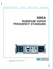
HP 5065A Operating And Service Manual (355 pages)
Rubidium Vapor Frequency Standard
Brand:
HP
| Category:
Laboratory Equipment
| Size: 32.3 MB
Table of Contents
Table of Contents
5
1 General Information
10
Introduction
10
Description
10
Options
10
Circuit Checks and Outputs
10
Terminology
10
Specifications
10
Instrument Identification
10
Equipment Supplied
11
Accessories Available
11
Specifications
12
2 II Installation
14
Installation
14
Unpacking and Inspection
14
Storage and Shipment
14
Environment
14
Extended Storage
14
RVFR Storage Procedure
14
Packaging
14
Electrical Connections
15
Power Connection
15
Mating Connectors
15
Operation as Bench or Rack Instrument
16
Installation Location
16
Mating Connectors
16
3 III Operation
17
Operation
17
Introduction
17
Operating Procedure
17
General
17
Turn-On Procedure (See Figure 3-2)
17
Turn-On after Long Storage
17
Frequency Offset and Calibration
18
Front Panel Lamp Indications
20
Frequency Comparison Using K34-59991A Linear Phase Detector
21
Typical Frequency Offset Change, Sample (Insufficient MAGNETIC FIELD Control)
23
Typical Frequency Offset Change, 0X10-10 Offset to -300X10-10
24
Operation with Time Standard Option 001 (or 003)
25
Setting the Clock Phase to an External Clock
25
Automatic Synchronization
25
Manual Synchronization
25
Setting the Clock
25
Offset Frequency Settings
26
Operation with Standby Power Supply Option
27
Synthesizer Setting Vs. Frequency Offset
27
Recommended Test Equipment
27
4 Theory of Operation
32
Theory
32
General
32
Option 001, Time Standard
33
Option 002, Standby Power Supply
34
Logic Signals
34
5 Vmaintenance
35
Introduction
35
Instrument Access
35
Periodic Maintenance
35
In-Cabinet Performance Check
36
Instrument Troubleshooting
40
Introduction
40
Fault Finding
41
Circuit Checks
42
Signal Checks
43
Recommended Test Equipment
45
Loop Alignment Procedure
46
Introduction
46
Volt Adjustment (A15 Power Supply and Regulator Assembly)
46
A10 Frequency Adjustment
46
Rfalignment
46
Signal-To-Noise Ratio
47
Modulation Frequency Adjustment
48
Phase Adjustment Recheck
48
Replaceable Parts
54
Manual Changes
83
A2 Battery Charger Assembly
85
Battery Charger Replaceable Parts
91
A4 100 Khz Frequency Divider Assembly
96
A4 100 Khz Divider Replaceable Parts
101
A1 Synthesizer Assembly Replaceable Parts
105
Synthesizer Assembly A1 Block Diagram
109
A1 Synthesizer Assembly
114
Synthesizer A1 Phase-Locked Oscillator Section
119
A7 AC Amplifier Assembly Replaceable Parts
131
A7 AC Amplifier Schematic Diagram
132
A16 Resistor Parts List
139
A5 Digital Divider Assembly (Option 001)
140
A16 Digital Divider Power Supply Assembly
145
A19 LED Digital Clock Assembly
159
A16 Resistor Parts List
166
A5 Digital Divider Assembly
169
A16 Digital Divider Power Supply Assembly
174
A5A4 Parts List
179
Block Diagram
182
Wiring Diagram (Sheet 1 of 3)
188
Wiring Diagram (Sheet 2 of 3)
192
Wiring Diagram (Sheet 3 of 3)
197
Synthesizer Assembly A1 Block Diagram Digital Section
202
Synthesizer Assembly A1 Digital Section (Sheet 1 of 2)
210
Synthesizer Assembly A1 Phase-Locked Oscillator Section (Sheet 2 of 2)
215
A2 Battery Charge Assembly (Option 002 and 003)
221
A3 Multiplier Assembly
228
A4 100 Khz Frequency Divider
234
A5A2 Master Clock Board (Option 001) (Sheet 2 of 3)
239
A5A3 Preset Clock Board (Option 001) (Sheet 3 of 3)
239
A6 1 Mhz Frequency Divider Assembly
263
A7 AC Amplifier Assembly
269
A8 Phase Detector Assembly
276
A9 Integrator Assembly
282
A10 Oscillator Assembly Block Diagram
289
A11 RVFR Temperature Controller Assembly
293
A12 RVFR Assembly and Buffer A13 Amplifier Assembly
301
A14 Logic Assembly
309
A15 Power Supply and Regulator Assembly
315
A16 Digital Divider Power Supply Assembly
321
Advertisement
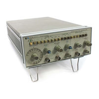
HP 5065A Operating And Service Manual (69 pages)
Function generator
Brand:
HP
| Category:
Inverter
| Size: 3.95 MB
Table of Contents
Warranty
3
Safety Information
3
Safety Symbols
3
Table of Contents
6
List of Tables
7
List of Illustrations
7
Safety Summary
8
Sweep Output. Output Level
10
Burst. Symmetry. Specifications
10
Instrument and Manual Identification
10
Specifications
11
General Information Table
11
Installation
12
Power Requirements. Grounding Requirements
12
Instrument Mounting. Repackaging for Shipment
12
Power Plugs Diagram
12
Operating Instructions
13
Controls and Indicators
13
General Operating Information
13
Generator Outputs
13
Front Panel Diagram
14
Rear Panel Diagram
15
Input Constraints
15
Mudulation Generator Input/Output
15
Output Characteristics
15
Sine Wave Output. Square Wave Output. Triangle Output
16
Ramp. Pulse. Gate or Burst. am
16
Phase Control of Burst Diagram
16
Percent Modulation Diagram
16
Basic Operating Procedures
17
Instrument Turn-On. Fuse Replacement
17
FM. SWP. External Control
17
Frequency. Amplitude
17
Main Generator Operation. Burst
18
Vco
18
Modulation Generator Operation
18
AM Operation Diagram
18
FM Operation Diagram
19
Sweep Operation Diagram
19
Burst Operation Diagram
20
Theory of Operation
21
Basic Block Diagram Description
21
Functional Block Diagram Description
22
Main Generator Section
22
Calibrated Symmetry Diagram
22
Variable Symmetry Diagram
22
Output Section
23
Modulation Generator
23
Level Shifter Diagram
23
Signal Generator Diagram
24
U403 Burst Amplifier Array Diagram
25
Burst Time Relation Waveforms Diagram
25
Required Test Equipment
27
Maintenance
28
Performance Tests
28
Dial Accuracy Test Table
28
Aberration Test
29
Triangle Linearity Test
29
Rise Time Test
29
Triangle Linearity (Positive Slope) Table
30
Triangle Linearity (Negative Slope) Table
30
Sweep Ramp Linearity Test
31
Linearity Table
32
Sine Wave Distortion Test
32
Output Impedance Test
33
Attenuator Accuracy Test
33
Sine Wave Level Flatness Test
33
Amplitude Flatness Diagram
33
Sync Output Impedance and Amplitude Test
34
Sync Output Rise and Fall Time Test. DC Offset Test
34
Internal Modulation Source Output Level Test
34
Internal Modulation Source Spectral Purity Test
34
Variable Symmetry Test
35
Carrier Envelope Distortion Test
35
External Amplitude Modulation Sensivitity Test
35
FM Distortion Test
35
Carrier 3 Db Bandwidth Test (Amplitude Modulation)
36
Frequency Deviation Test
36
FM Distortion Diagram
36
External Frequency Control Input Requirements, VCO Linearity Tests
37
VCO Linearity Graph
37
Adjustment Procedures
38
Power Supply Adjustment
38
Frequency Adjustment
38
Distorstion Adjustment
39
Rise Time and Aberration Adjustment
39
Modulation Symmetry Adjustment
39
Modulation Sinewave Distortion Adjustment
39
Factory Selected Values
40
Factory Selected Components Table
40
Carrier Balance Adjustment
40
Adjustment Locator Diagram
41
Performance Test Card
42
Replaceable Parts
44
Ordering Information
44
Chassis Mounted and Miscellaneous Parts. Non-Listed Parts
44
Standard Abbreviations Table
44
Code List of Manufacturers
45
Replaceable Parts Table
46
Chassis Mounted Components Picture
55
3312A Jack Connections
56
General Schematic Notes
56
Circuit Diagrams
57
Reference Designators
57
Troubleshooting
57
Functional Block Diagram
57
3312A Settings Table
58
Tuning Amplifier Integrator and Ranges Switches Diagram
60
3312A Settings
64
Backdating
66
HP 5065A Manual (31 pages)
RUBIDIUM VAPOR FREQUENCY STANDARD
Brand:
HP
| Category:
Measuring Instruments
| Size: 1.61 MB
Table of Contents
Warranty
2
Older Instruments
3
Hewlett Packard
3
Ac Power Cord
5
Rack Mount Kit
5
Accessory Kit
5
Atomic Time
6
Mating Connectors
8
Installation
10
Unpacking and Inspection
10
Storage and Shipment
10
Operation as Bench or Rack Instrument
12
Installation Location
12
Operation
13
Power Supply \A
14
Theory of Operation
28
Option 001, Time Standard
29
Option 002, Standby Power Supply
30
Advertisement
Advertisement
Related Products
HP 5314A
HP 5316B
HP 54120B
HP 59307A VHF
HP 581A
HP 580A
HP HP 5348A
HP 5334A
HP 5334B
HP 54200A
HP Categories
Desktop
Laptop
Server
Monitor
Switch
More HP Manuals
Login
Sign In
OR
Sign in with Facebook
Sign in with Google
Upload manual
Upload from disk
Upload from URL