Sign In
Upload
Manuals
Brands
HP Manuals
Control Unit
16600A Series
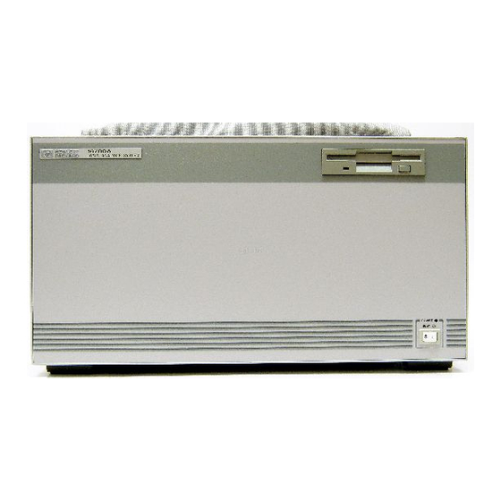
HP 16600A Series Manuals
Manuals and User Guides for HP 16600A Series. We have
3
HP 16600A Series manuals available for free PDF download: User Manual, Installation Manual
HP 16600A Series User Manual (297 pages)
Solutions for the Motorola CPU32
Brand:
HP
| Category:
Measuring Instruments
| Size: 6.61 MB
Table of Contents
HP Solutions for the Motorola CPU32-At a Glance
3
In this Book
5
Table of Contents
6
Overview
17
Setup Checklist
18
Setup Assistant
20
Analysis Probe
21
Equipment Supplied
21
Minimum Equipment Required
23
Additional Equipment Supported
23
Logic Analyzers Supported
24
Logic Analyzer Software Version Requirements
25
Emulation Module
26
Equipment Supplied
26
Minimum Equipment Required
27
Emulation Solution
28
Additional Information Sources
29
Installing Software
31
Installing and Loading
31
What Needs to be Installed
32
To Install the Software from CD-ROM (HP 16600A/700A)
33
To List Software Packages Which Are Installed (HP 16600A/700A)
34
To Install Software on Other Logic Analyzers
34
Connecting and Configuring the Analysis Probe
36
Connecting and Configuring the Analysis Probe
37
Target System Requirements
38
Analysis Probe-Circuit Board Dimensions
39
Power-On/Power-Off Sequence
40
To Power on HP 16600A and HP 16700A-Series Logic Analysis Systems
40
To Power on All Other Logic Analyzers
40
To Power off
41
Connecting the Analysis Probe to the Target System
43
To Connect the Transition Board
44
To Connect the Analysis Probe to the Probe Adapter
45
Connecting the Probe Adapter to the Target System
46
Connecting the Analysis Probe to the Logic Analyzer
50
To Connect the High-Density Termination Cables to the Analysis Probe
51
Connecting the High-Density Cables to the Logic Analyzer
52
To Connect to the HP 16600A Logic Analyzer
53
To Connect to the HP 16601A Logic Analyzer
55
To Connect to the HP 16602A Logic Analyzer
57
To Connect to the HP 16603A Logic Analyzer
59
To Connect to the HP 16550A Analyzer
61
To Connect to the HP 16554/55A/56/57D Analyzers
64
To Connect to the HP 1660A/AS/C/CS/CP Logic Analyzers
66
To Connect to the HP 1661A/AS/C/CS/CP Logic Analyzers
68
To Connect to the HP 1662A/AS/C/CS/CP Logic Analyzers
70
To Connect to the HP 1670A/D Logic Analyzer
72
To Connect to the HP 1671A/D Logic Analyzer
74
To Connect to the HP 1672A/D Logic Analyzer
76
Configuring the Analysis Probe
78
To Set the ID Switches
79
To Interpret the Leds
80
Configuring the Analysis Probe for Address Reconstruction
82
To Configure with a Debugger
82
To Configure with a Logic Analysis System
83
Configuring the Logic Analysis System
84
Systems
85
To Load Configuration Files-Other Logic Analyzers
86
Analyzing the CPU32 with a Logic Analyzer
90
Analyzing the CPU32 with a Logic Analyzer
91
Modes of Operation
92
State Mode
92
Timing Mode
92
Logic Analyzer Configuration
93
Trigger Specification
93
Format Menu
93
To Qualify Stored Data
99
Using the Inverse Assembler
100
To Display Captured State Data
100
To Align the Inverse Assembler
102
Inverse Assembler Output Format
103
To Use the Invasm Menu
105
Inverse Assembler Error Messages
107
Symbols and Source Code in the Analyzer
108
Symbols and Source Code in the Analyzer
109
User-Defined Symbols
110
Predefined CPU32 Symbols
110
Object File Symbols
111
Requirements
111
To Use Object File Symbols in the HP 16600A/700A
112
Compilers
113
Source Code
117
Inverse Assembler Generated PC (Software Address) Label
119
Access to Source Code Files
120
Triggering on Symbols and Source Code
121
To Avoid Triggering on Prefetched Instructions
121
To Correlate Relocatable Code Using the Address Offset
122
Connecting and Configuring the Emulation Module
124
Connecting and Configuring the Emulation Module
125
Using the Emulation Control Interface
126
To Start the Emulation Control Interface from the Main System Window
128
To Start the Emulation Control Interface from the Workspace Window
128
To Start the Emulation Control Interface from the Workspace Window for an Emulation Probe
130
Designing a Target System for the Emulation Module
131
Debug Port Connections
131
8-Pin BDM Port
133
Target V
133
Enabling BDM
134
Installing the Emulation Module
135
To Install the Emulation Module in an HP16700A-Series Logic Analysis System or an HP16701A Expansion Frame
136
To Install the Emulation Module in an HP16600A-Series Logic Analysis System
138
To Test the Emulation Module
139
Connecting the Emulation Module to the Target System
140
To Connect to a Target System Using a 10-Pin Debug Port
141
To Connect to a Target System Via an 8-Pin Debug Port
142
To Connect to a Target System Using an Analysis Probe
144
To Update Firmware
145
To Display Current Firmware Version Information
146
To Verify Communication between the Emulator and Target System
146
Configuring the Emulation Module
147
What Can be Configured
147
To Configure Using the Emulation Control Interface
148
To Configure Using the Built-In Commands
149
To Configure Using a Debugger
150
To Configure the Processor Type
151
To Configure the Processor Clock Speed (BDM Communication Speed)
152
To Set the Default Clock Rate if the Processor Clock Rate Is Less than 8 Mhz
153
Detailed Information about Processor Clock Rates
155
To Configure Restriction to Real-Time Runs
157
Testing the Emulator and Target System
158
To Test Memory Accesses
158
To Test with a Running Program
158
Using Internal Registers (SIM and EMSIM Registers)
160
Internal Registers (SIM and EMSIM Registers)
161
The Purpose of SIM Registers
161
The Purpose of EMSIM Registers
161
Configuring the SIM Registers
162
Summary
162
How SIM Register Values Are Set
162
The Effect of Processor Type on the EMSIM Registers
163
Using the Emulation Control Interface or Built-In Commands
163
Configuring EMSIM Register Values
164
To Copy Target SIM Registers to EMSIM Registers
164
To Manually Define EMSIM Values
164
Configuring SIM Register Values
166
To Copy EMSIM Registers to Target SIM Registers
166
To Manually Define SIM Values
167
Saving and Loading EMSIM Values
168
To Save EMSIM Values in a Configuration File
168
To Load EMSIM Values from a Configuration File
168
Configuring SIM and EMSIM Values Using Built-In Commands
170
To Compare SIM and EMSIM Registers
170
Summary of EMSIM-Related Built-In Commands
171
Advertisement
HP
16600A Series
Installation Manual
HP 16600A Series Installation Manual (120 pages)
Measurement Modules
Brand:
HP
| Category:
Control Unit
| Size: 7.58 MB
Table of Contents
Table of Contents
3
System Overview HP 16600A Series
4
System Overview HP 16700A
5
System Overview HP 16702A
6
HP 16600A Series, HP 16700A, HP 16702A
7
Mouse and Keyboard
7
Monitor Connection
8
Proper Cooling
9
Monitor Configuration
10
Changing Monitors
12
Lan
13
Printers
14
CD-ROM Drive
16
External Disk Drive
18
CD-ROM Drive & External Disk Drive
20
Software Installation
22
HP 16701A Expander Frame
25
Probing
26
Self-Test
32
Specifications & Characteristics
33
Disaster Recovery
34
Proper Cleaning
38
Measurement Modules
40
General Installations
41
Hp 16517/18A
48
Hp 16522A
49
Hp 16557D
69
Hp 16710/11/12A
74
Hp E2485A
82
HP 16600A Series Installation Manual (110 pages)
Measurement Modules, Logic Analysis Systems
Brand:
HP
| Category:
Measuring Instruments
| Size: 29.19 MB
Advertisement
Advertisement
Related Products
HP 16610A
HP ProCurve Wireless 170wl
HP 16700A
HP 16702A
HP 10GbE Pass-Thru Module
HP 10529A
HP Compaq Presario,Presario 1660
HP 1660CS
HP HP 1660CP Series
HP 1660E Series
HP Categories
Desktop
Laptop
Server
Monitor
Switch
More HP Manuals
Login
Sign In
OR
Sign in with Facebook
Sign in with Google
Upload manual
Upload from disk
Upload from URL