Sign In
Upload
Manuals
Brands
Honeywell Manuals
Media Converter
WD770-180A-4
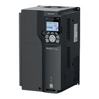
Honeywell WD770-180A-4 Manuals
Manuals and User Guides for Honeywell WD770-180A-4. We have
1
Honeywell WD770-180A-4 manual available for free PDF download: User Manual
Honeywell WD770-180A-4 User Manual (208 pages)
WellDrive Frequency Converters
Brand:
Honeywell
| Category:
Media Converter
| Size: 16.37 MB
Table of Contents
Table of Contents
3
Chapter - 1: Safety Precautions
11
What this Chapter Contains
11
Safety Defini�On
11
Warning
11
Safety Guidelines
12
Delivery and Installa�On
12
Comissioning and Running
13
Maintenance and Component Replacement
13
Disposal
13
Chapter - 2: Quick Startup
14
What this Chapter Contains
14
Unpacking Inspec�On
14
Checking before Use
14
Environment Checking
14
Checking A�Er Installa�On
14
Basic Commissioning
15
Chapter - 3: Product Oerview
15
What this Chapter Contains
15
Basic Principles
15
Product Specifica�Ons
16
Product Nameplate
17
Model Designa�On Code
17
Product Ra�Ngs
18
Structure
19
Chapter - 4: Installation Guidelines
20
What this Chapter Contains
20
Mechanical Installa�On
20
Installa�On Environment
20
Installa�On Direc�On
21
Moun�Ng Method
21
Installing VFD
22
Ver�Cal Installa�On
22
Tilted Installa�On
23
Cabinet Installa�On
23
Heat Dissipa�On Descrip�On
23
Points for Aten�On
24
In-Cabinet Moun�Ng Procedure
25
Standard Wiring of the Main Circuit
28
Main Circuit Wiring Diagram
28
Main Circuit Terminal Diagram
29
Wiring Procedure for Main Circuit Terminals
33
Standard Wiring of the Control Circuit
33
Wiring Diagram of Basic Control Circuit
33
Input/Output Signal Connec�On Diagram
35
External Op�Onal Keypad Wiring
36
Wiring Protec�On
36
Protec�Ng the VFD and Input Power Cable in Case of Short Circuit
36
Protec�Ng the Motor and Motor Cable in Case of Short Circuit
37
Protec�Ng the Motor against Thermal Overload
37
Bypass Connec�On
37
Chapter - 5: Basic Operation Guidelines
38
What this Chapter Contains
38
Keypad Opera�On
38
LED Keypad (WDM-BOP-1) Display and Opera�On
38
Displaying Stopped-State Parameters
40
Displaying Running-State Parameters
40
Displaying Fault Alarms
40
Edi�Ng Func�On Codes
40
Modifying Func�On Codes
41
Se�Ng a Password for the VFD
41
Se�Ng a Password
42
LCD Keypad (WDM-LCD-1) Display and Opera�On
42
Displaying Stopped-State Parameters
44
Displaying Running-State Parameters
44
Displaying Fault Informa�On
45
Entering / Exi�Ng Menus
45
Edi�Ng a Parameter List
48
Adding Parameters to the Parameter List Displayed in Stopped/Running State
49
Adding Parameters to the User Defined Parameter List
50
Edi�Ng User Defined Parameters
50
Edi�Ng Parameters in Parameter Groups
51
Monitoring States
51
Autotuning Motor Parameters
51
Backing up Parameters
52
System Se�Ngs
52
Power-On Setup Wizard
53
Basic Opera�On Descrip�On
54
What this Sec�On Describes
54
Common Commissioning Procedure
54
Vector Control
56
Advanced Scalar Control Mode
59
Torque Control
64
Motor Parameters
67
Start/Stop Control
69
Frequency Se�Ng
73
Analog Input
75
Analog Output
76
Digital Input
76
Digital Output
77
Simple PLC
77
Mul�-Step Speed Running
78
PID Control
78
General Procedures for PID Parameter Setup
79
How to Fine-Tune PID
80
Water Pump Control
80
Motor Adding or Reducing
84
Polling Func�On
87
Water Pump Maintenance
87
Smooth Switchover
87
Fixed Variable-Frequency Run Mode
88
PID Func�On Only for Water Supply
89
Segmented Water Pressure
89
Automa�C Sleep
89
Pump Cleaning
90
Water Pipe Break Detec�On
90
Water Pipe So� Padding
91
Freezing Protec�On
91
Condensa�On Protec�On
92
Chapter - 6: Function Parameter List
92
What this Chapter Contains
92
Func�On Parameter List
92
P00 Group-Basic Func�Ons
93
P01 Group-Start & Stop Control
95
P02 Group - Parameters of Motor 1
97
P03 Group--Vector Control of Motor 1
98
P04 Group-Imporved Scaler (V/F) Control
101
P05 Group - Input Terminals
104
P06 Group-Output Terminals
106
P07 Group - Human Machine Interface
108
P08 Group - Enhanced Func�Ons
112
P09 Group - PID Control
116
P10 Group - Simple PLC and Mul�-Step Speed Control
118
P11 Group - Protec�On Parameters
121
P12 Group - Parameters of Motor 2
127
P13 Group - SM Control
129
P14 Group - Serial Communica�On
130
P15 Group - Func�Ons of Communica�On Expansion Card 1
131
P16 Group - Func�Ons of Communica�On Expansion Card 2
131
P17 Group - Status Viewing
131
P19 Group - Expansion Card Status Viewing
133
P23 Group - Vector Control of Motor 2
134
P25 Group -Input Func�Ons of Expansion I/O Card
134
P26 Group - Output Func�Ons of Expansion I/O Card
136
P28 Group - Master / Slave Control
137
P89 Group - HVAC Status Viewing
138
P90 Group - PID1 Control
139
P91 Group - PID2 Control
141
P92 Group - Real Time Clock and Timer
142
P93 Group - Fire Mode
143
P94 Group - HVAC Func�Ons
143
P95 Group--Segmented Water Pressure
145
P96 Group - HVAC Protec�On
146
Value Coded Parameters
147
P05.08 : Input Terminal Polarity
147
P07.05 : Selec�On 1 of Parameters Displayed in Running State
148
P07.06 : Selec�On 2 of Parameters Displayed in Running State
149
P07.07 : Selec�On of Parameters Displayed in Stopped State
150
P07.39 : Input Terminal Status at Present Fault
150
P25.08 : Expansion I/O Module Input Terminal Polarity
151
P25.09 : Expansion I/O Module Virtual Input Terminal Se�Ng
151
P26.12 : Relay Module Output Terminal Polarity
151
P89.02 : Mul�-Motor Validity Status
152
P89.03 : Power-Frequency Motor Run Status
152
Chapter - 7: Troubleshooting
153
What this Chapter Contains
153
Indica�Ons of Alarms and Faults
153
Fault Reset
153
Fault History
153
Faults and Solu�Ons
153
Other Status
156
Analysis on Common Faults
157
Motor Vibrates
157
Overvoltage
158
Undervoltage
158
Motor Overhea�Ng
159
VFD Overhea�Ng
159
Motor Stalls During ACC
159
Overcurrent
160
Countermeasures on Common Interference
161
Interference on Meter Switches and Sensors
161
Interference on RS485 Communica�On
161
Failure to Stop and Indicator Shimmering Due to Motor Cable Coupling
162
Leakage Current and Interference on RCD
162
Live Device Chassis
163
Chapter - 8: Maintenance
164
What this Chapter Contains
164
Periodical Inspec�On
164
Cooling Fan
165
Capacitor
166
Capacitor Reforming
166
Electroly�C Capacitor Replacement
167
Power Cable
167
Chapter - 9: Communication Protocol
167
What this Chapter Contains
167
Modbus Protocol Introduc�On
167
Applica�On of Modbus
167
Rs485
167
Applica�On to Single VFD
168
Applica�On to Mul�Ple Vfds
168
RTU Mode
169
RTU Communica�On Frame Structure
169
RTU Communica�On Frame Error Check Methods
170
RTU Command Code and Communica�On Data
171
Command Code 03H, Reading N Words (Con�Nuously up to 16 Words)
171
Command Code 06H, Wri�Ng a Word
172
Data Address Defini�On
174
Func�On Code Address Format Rules
174
Addresses of Other Modbus Func�Ons
175
Fieldbus Scale
177
Error Message Response
177
Read/Write Opera�On Examples
178
Read Command 03H Examples
178
Write Command 06H Examples
179
Parameter Quan�Ty
180
Common Communica�On Faults
180
Appendix - A: Appendix A Expansion Card
181
Model Defini�On
181
Dimensions and Installa�On
181
Wiring
183
I/O Modules
184
Wdm-Io-1
184
Wdm-Ro-1
185
Communica�On Cards
186
A.5.1 PROFIBUS Communica�On Card (WDM-PB-1)
186
CAN Mul�-Protocol Communica�On Card (WDM-CO-1)
187
PROFINET Communica�On Card (WDM-PN-1)
188
APPENDIX- B: Appendix B Technical Data
189
What this Chapter Contains
189
Derated Applica�On
189
Capacity
189
Dera�Ng
189
Dera�Ng Due to Temperature
189
Dera�Ng Due to Al�Tude
189
Dera�Ng Due to Carrier Frequency
189
Grid Specifica�Ons
189
Motor Connec�On Data
189
EMC Compa�Bility and Motor Cable Length
190
Applica�On Standards
190
CE Marking
190
EMC Compliance Declara�On
190
EMC Regula�Ons
190
APPENDIX - C: Dimension Drawings
191
What this Chapter Contains
191
Keypad Structure
191
Structure Diagram
191
Keypad Moun�Ng Bracket
191
WD770 Structure
192
Phase 380 Vac Input WD770 VFD Models
192
Wall-Moun�Ng Dimensions
192
Flange Moun�Ng Dimensions
195
Floor Moun�Ng Dimensions
197
APPENDIX - D: Optional Peripheral Accessories
198
What this Chapter Contains
198
Wiring of Peripheral Accessories
198
Power Supply
198
Cables
198
Power Cables
198
Control Cables
199
Recommended Cable Size
199
Cable Arrangement
201
Insula�On Inspec�On
201
Breakers and Electromagne�C Contactors
201
Reactors
202
Filters
203
Input Filters
203
SCHAFFNER Input Filters
203
FLT Input Filters
204
Output Filters
205
List of Other Op�Onal Accessories
205
Appendix - E: Energy Efficiency Data
206
Appendix - E: Further Information
207
Product and Service Queries
207
Feedback on Welldrive VFD Manuals
207
Documents on the Internet
207
Advertisement
Advertisement
Related Products
Honeywell WD770-13A-4
Honeywell WD770-17A-4
Honeywell WD770-115A-4
Honeywell WD770-150A-4
Honeywell WD770-9A5-4
Honeywell WD770-25A-4
Honeywell WD770-860A-4
Honeywell WD770-650A-4
Honeywell WD770-530A-4
Honeywell WD770-460A-4
Honeywell Categories
Thermostat
Controller
Control Unit
Security Camera
Accessories
More Honeywell Manuals
Login
Sign In
OR
Sign in with Facebook
Sign in with Google
Upload manual
Upload from disk
Upload from URL