Sign In
Upload
Manuals
Brands
Honeywell Manuals
Receiver
Limitless WMPR Series
Honeywell Limitless WMPR Series Manuals
Manuals and User Guides for Honeywell Limitless WMPR Series. We have
1
Honeywell Limitless WMPR Series manual available for free PDF download: Installation And Technical Manual
Honeywell Limitless WMPR Series Installation And Technical Manual (46 pages)
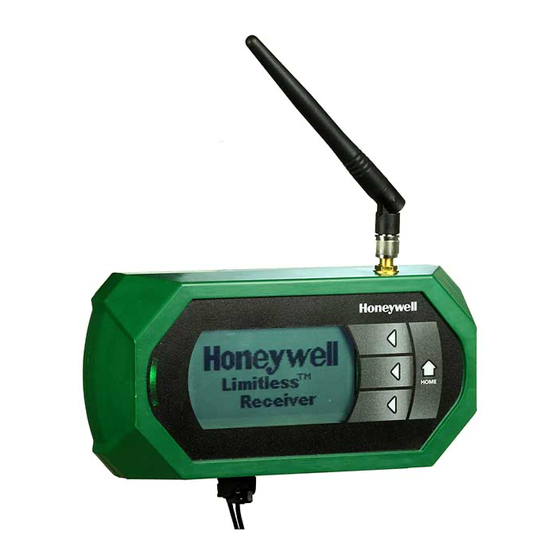
Multi-Protocol Receiver
Brand:
Honeywell
| Category:
Receiver
| Size: 9.91 MB
Table of Contents
Table of Contents
2
1 Product Description
5
General
5
Principle of Operation
5
Product Nomenclature
6
Figure 1. WMPR Series Nomenclature
6
Abbreviations & Definitions
7
Symbols & Definitions
8
Table 2. Symbol Definitions
8
2 Specifications, Certifications
9
And Approvals
9
Intended County Usage
9
Certifications and Approvals
9
Radio Module Specifications
9
Electrical Specifications
9
Table 3. North America: Country Code Use "A
9
Table 4. Asia Pacific: Country Code Use "B
9
Table 5. Communication Approvals and Standards
9
Table 6. Radio Module Specifications
9
Table 7. Electrical Specifications
9
Operational Characteristics
10
Update Rate Vs. Node Quality
10
Update Rate Vs. RF Lost Indication
10
EMC Specifications
10
Environmental Specifications
10
Weight
10
Antenna Connection
10
Agency Compliance Statements
10
FCC Compliance Statements
10
Table 8. WPS Series Sensors Update Rate
10
IC Compliance Statements
11
RF Safety Statements (FCC & IC)
11
3 Wmpr Features
12
LED Indicator
12
Figure 2. Limitless™ WMPR with Callouts
12
Table 12. LED Indicators
12
Limitless™ Switch and Sensor Buttons
13
Figure 3A. Limtless™ WBX Function Button and LED
13
Figure 3B. Limtless™ WLS Function Button and LED
13
Figure 3C. Limtless™ WPS Reset Button and LED
13
4 F. Interfer. Considerations
14
RF Interference Considerations
14
General
14
Wifi Networks
14
Smart Phone "Apps
14
Bluetooth Devices
14
Wireless Video Camera & Links
14
Microwave Ovens
14
Cordless Phones/Baby Monitors
14
5 Setup and Electrical
15
Configurations
15
System Set up
15
WMPR EDS File
15
WMPR Object Model
15
Static IP Address (ON/OFF DHCP Server)
15
Ethernet/Ip™ Output Connection
15
Description
15
Table 13. Conformance Advisories & Warnings
15
Power Supply Connections
16
Description
16
6 Lcd/Menu/Mode Operation
16
Start-Up or Re-Start-Up Mode
16
Zero Switches or Sensors Paired
16
One or more Switches or Sensors
16
Figure 4. Honeywell Splash Screen
16
Figure 5. Ethernet/Ip™ MAC ID & IP Address
16
Figure 6. Main Menu
16
Figure 7. Honeywell Splash Screen
16
Main Menu
17
Menu Status
17
Ethernet/Ip™ Connection
17
Figure 8. System Start up
17
Figure 9. Ethernet/Ip™ MAC ID & IP Address
17
Figure 10. Main Menu
17
Figure 11. Main Menu
17
Figure 12. Main Menu - Ethernet Lost
17
Node Information
18
Node Status
18
Node Status Menu
18
Action Menu
18
Figure 13. Main Menu - RF Lost Screen Display
18
Figure 14. Node Status
18
Figure 15. Action Menu
18
Table 14. Node Display and Indication
18
Node Detail
19
Node Detail Menu, Screen 1
19
Node Detail Menu, Screen 2
19
Figure 16. Node Detail Menu
19
Figure 17. Node Detail, Screen 1
19
Figure 18. Node Detail, Screen 2
19
Table 15. Node Display and Indication, Screen 1
19
Table 16. Node Display and Indication, Screen 2
19
Node Detail Menu, Screen 3
20
Configuration Menu
20
Figure 19. Node Detail, Screen 3
20
Figure 20. Configuration Menu
20
Figure 21. Configuration Menu, Continued
20
Table 17. Node Display and Indication, Screen 3
20
Receiver Detail
21
Pair Mode
21
Figure 22. Receiver Detail Menu
21
Figure 23. Receiver Information, Screen 1
21
Figure 24. Receiver Information, Screen 2
21
Figure 25. Pair Mode
21
Table 18. Receiver Detail and Display, Screen 1
21
Table 19. Receiver Detail and Display, Screen 2
21
Figure 26. Pairing in Progress
22
Figure 27. Join Network Notice (Switch)
22
Figure 28. Join Network Notice (Analog Sensor)
22
Table 20. Pair Mode
22
Purge Mode
23
Node Update Rate Mode
23
Figure 29. Purge Mode
23
Figure 30. Purge Mode - Purge Update Sent
23
Figure 31. Purge Mode - Single Node Being Purged
23
Figure 32. Purge Mode - Multiple Nodes Being Purged
23
Figure 33. Node Update Rate Mode
23
Node LCD Display Mode
24
Figure 34. Node Update Rate - Update Rate in Progress
24
Figure 35. Node Update Rate - Update Rate Displayed
24
Figure 36. Node Update Rate - Changed Update Rate
24
Figure 37. Node LCD Display Mode
24
Figure 38. Node LCD Time
24
Factory Reset Receiver Mode, GEN 1
25
Figure 39. Node LCD Time - Time Displayed
25
Figure 40. Node LCD Time - Updated LCD Time
25
Figure 41. Factory Reset Mode
25
Figure 42. Reset of Receiver, GEN 1 Only
25
Figure 43. Network Start Notice
25
Factory Reset Receiver Mode, GEN 2
26
Reset All Nodes from WMPR
26
Figure 44. Reset of Receiver, GEN 2 Only
26
7 Antenna, Cabling, & Mounting
27
Antenna, Cabling, & Mounting
27
Approved Antenna Options
27
Table 21. Country Code Use "A" Options
27
Table 22. Country Code Use "B" Options
28
8 Antenna Selection
29
Adjustment & Mounting
29
Warnings
29
Antenna Designs & Considerations
30
Omni-Directional Antenna Design
30
Figure 45. Radiation Pattern/Omni-Directional Antenna
30
Antenna Mounting & Considerations
31
Mounting to RF Signal
31
Figure 46. LOS Free from Obstacles
31
Figure 47. LOS Affected by Obstacles
31
Antenna Options
32
Table 23. Antenna Options
32
Antenna Connections & Options
33
Antenna Connection
33
Figure 48. Limitless™ RP-SMA Connection, Direct
33
Figure 49. Limitless ™ RP-SMA Connection, Remote
33
Cable Requirement
34
Antenna Styles & Mounting Options
34
Figure 50. Adhesive Mounting Steps
34
Antenna Adjustment Considerations
35
Figure 51. Mast Mount Antenna
35
Figure 52. Mast Mount Antenna, Side View
35
Figure 53. Magnetic Base Mount Antenna
35
Figure 54. Magnetic Mount Antenna
35
Figure 55. Magnetic Mount Antenna
35
Figure 56. Thru-Hole Mount Antenna
35
Grounding Remote Antennas
36
Figure 57. Highest RF Signal Diagram
36
Table 24. Grounding the Antenna
36
Antenna Environmental Usage
37
Meet Application Exposure Conditions
37
Protection of Antenna Connections
37
Figure 58. Application of Protective Tape
37
Outdoor Antenna Installations
38
Lightning Arrestor
38
Site Selection
38
Mounting in Respect to Location
38
Gain with Acceptable Fade-Margin
38
9 Wmpr Mounting
40
DIN Rail Mounting
40
Tab Mounting
40
10 Inspection and Maintenance
40
WMPR Inspection and Replacement
40
Antenna Inspection and Replacement
40
Figure 59. Limitless™ WMPR DIN Rail Bracket
40
Figure 60. Limitless™ WMPR Mounting Plate
40
11 Choosing a Catalog Listing
41
12 Quick Start up and Installation
41
Figure 61. WMPR Series Nomenclature
41
Table 25. Suggested Start-Up Sections to Review
41
13 Accessories
42
Table 26. Limitless™ Antennas
42
Table 27. Limitless™ Cables
43
Table 28. Limitless™ Base Accessories
43
14 Installation Drawing
44
Figure 62. WMPR Dimensions
44
Advertisement
Advertisement
Related Products
Honeywell Limitless WDRR Series
Honeywell Limitless WGLA Series
Honeywell Limitless WPMM Series
Honeywell Limitless WLS Series
Honeywell Limitless Series
Honeywell Fire Lite Alarms SWIFT
Honeywell Linear Series
Honeywell L91D
Honeywell Aquastat L8148J
Honeywell Notifier LCD2-80
Honeywell Categories
Thermostat
Controller
Control Unit
Security Camera
Accessories
More Honeywell Manuals
Login
Sign In
OR
Sign in with Facebook
Sign in with Google
Upload manual
Upload from disk
Upload from URL