Sign In
Upload
Manuals
Brands
Honeywell Manuals
Automobile Accessories
KTA 870
Honeywell KTA 870 Manuals
Manuals and User Guides for Honeywell KTA 870. We have
2
Honeywell KTA 870 manuals available for free PDF download: Installation Manual, System Installation Manual
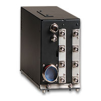
Honeywell KTA 870 Installation Manual (343 pages)
BENDIX/KING MULTI-HAZARD AWARENESS TRAFFIC ADVISORY SYSTEM
Brand:
Honeywell
| Category:
Automobile Accessories
| Size: 5.77 MB
Table of Contents
Table of Contents
7
Introduction
15
General Information
15
Basic EGPWS System
16
System Description
16
Table 1-1 KMH 880/KTA 870 Applicable Versions
16
System Components
17
Basic TAS System
17
KMH 880 SYSTEM PRIMARY Lrus
18
KTA 870 SYSTEM PRIMARY Lrus
18
Table 1-2 KMH 880 Lrus
18
Table 1-3 KTA 870 Lrus
18
EGPWS Modes of Operation
20
EGPWS System
20
Figure 1-1 KMH 880/KTA 870 System
20
Optional Alerting and Warning Parameters
20
GPS Sensor
21
Setup Mode
21
Standby Mode
21
TAS Modes of Operation
21
Altitude Monitor Option
22
Display Option
22
TAS Operation (Traffic Advisory) Mode
22
TAS Processor
22
KMH 820 W/O GPS Multi-Hazard Awareness Unit Technical Specifications
23
Outside Air Temperature (OAT) (Recommended)
23
Technical Characteristics
23
KMH 820 W/ GPS Multi-Hazard Awareness Unit Technical Specification
24
Table 1-6 KTA 810 Traffic Advisory Unit Technical Specifications
24
Table 1-7 KCM 805 Configuration Module Technical Specifications
25
Table 1-8 KA 815 Traffic Antenna Technical Specifications
25
KMH 820/KTA 810 Processor Units
26
TAS Processor Unit
26
Unit and Accessories Supplied
26
Table 1-9 KA 92 GPS Antenna Technical Specifications
26
Table 1-11 KCM 805 Configuration Module
27
Table 1-12 KA 815/KA 92 Antennas
27
KMH 820/KTA 810 Installation Kit
28
Installation Accessories Supplied
28
Table 1-13 GPS Cable Run Lengths
28
Antenna Installation Kits
29
Table 1-14 KMH 820/KTA 810 Installation Kit
29
Table 1-15 KA 815 Installation Kit
29
Table 1-16 KA 92 Installation Kit
29
Accessories Required but Not Supplied
30
GPS Antenna Splitter
30
Databases
30
Table 1-18 Temperature Probe
30
License Requirements
31
Table 1-19 GPS Antenna Splitter
31
Table 1-20 Miscellaneous Accessories
31
Table 1-21 Cable and Wire
31
Annunciators/Relays
32
GPS Antenna
32
KMH 820/KTA 810 Unit
32
Instructions for Continued Airworthiness
32
Wires and Coax Cables
33
Terrain Data Base Updates
33
Temperature Probe
33
Installation
35
Unpacking and Inspecting Equipment
35
Equipment Installation
35
Introduction
35
Avionics Cooling Requirements
36
Cooling Considerations
37
Installation Considerations
37
Processor Installation
37
Installation Procedure
39
Configuration Module Installation
45
Antenna Location
49
Directional Antenna Installation
49
KA 815 Antenna Outline Drawing
51
Gps Antenna Installation
53
KA 92 Antenna Installation Considerations
53
TAS Coaxial Cable Fabrication
62
GPS Coaxial Cable Fabrication
63
Signal Loss
63
Bulkhead/In-Line Connection RG-400 Coax Cable
64
Coax Cable Treatment
64
Standard RG-400 Coax Cable
64
TNC Antenna Coax/Connector Assembly
65
Applicable Part Numbers Sub-Section Description
67
Function Sub-Section Description
67
Requirements and Limitations Sub-Section Description
67
System Planning
67
Interface Subsection Description
68
Figure 3-1 KMH 880/KTA 870 Interconnect Family
69
General Interconnect Information
71
On Discrete
71
Power Inputs
71
Air/Ground Discrete Input
72
Landing Gear Discrete Input
72
Above/Below/Normal Input
73
Advisory Inhibit Input
73
Baro Altitude (ARINC 429) Input
73
Synthesized Voice Output
74
TAS Valid Output
74
Visual Annunciate Traffic (Lamp Output)
74
Air Temperature Input
75
GPS Input
75
Factory Test Input
76
TAS ATE Enable Input
76
TAS Built in Test Equipment (BITE)
76
EGPWS Self Test Input
77
Failure Categories
77
Failure Processing
77
Display Select Input
78
Terrain Awareness Inhibit Discrete
78
Terrain Caution
78
Terrain Warning
78
EGPWS Audio on Discrete
79
EGPWS, Terrain Inop and Terrain Not Available Output
79
Figure 3-2 KMH 820/KTA 810 Pinout Diagram
81
Figure 3-3 KMH 820/KTA 810 System Interconnect Block Diagram
95
Figure 3-4 KMH 820/KTA 810 Power Interface
99
Figure 3-5 KMH 820/KTA 810 Discrete Interface
101
Figure 3-6 KMH 820/KTA 810 Configuration Module Interconnect
103
Figure 3-7 KMH 820/KTA 810 Attitude/Heading Interface
105
Figure 3-8 KMH 820/KTA 810 Radar/Barometric Altitude Interface
107
Figure 3-9 KMH 820/KTA 810 Antenna/Suppression Interface
115
Figure 3-11 KMH 820/KTA 810 GC 362A Interface
119
Figure 3-14 KMH 820/KTA 810 Honeywell Primus 1000 Interface
135
Figure 3-15 KMH 820/KTA 810 Honeywell SPZ-805 Interface
139
Figure 3-16 KMH 820/KTA 810 Diagnostic/Data Recorder Interface
143
Figure 3-17 KMH 820/KTA 810 TAS ATE Interface
145
Figure 3-18 KMH 820/KTA 810 CP 66B Interface
147
Figure 3-19 KMH 820/KTA 810 KFS 578A Interface
149
Figure 3-22 KMH 820/KTA 810 Processor Front Connector
205
Figure 3-23 KMH 820/KTA 810 Front Connector Cable
206
Figure 3-24 KMH 820/KTA 810 Rear Connector Cable
207
KMH 820/KTA 810 Connector Pin Assignment
208
Certification
211
Certification Procedure
211
Equipment Compatibility
211
Equipment Location
211
FAA Form 337
212
FAA Requirements
212
Federal Communication Commission Rules
212
TSO Category
212
Flight Manual Revision
213
Pilot Briefing
213
Operation
215
Mode C Surveillance Range
219
Mode C Surveillance Range Ontop Antenna
219
Sample Certification Checklist
227
Diagnostic Appendices
230
TASDIAG-TAS Processor Field Diagnotic Program User Instructions
230
Table of Contents
231
Computer Requirements
233
Introduction
233
Installing the TAS Diag Program
234
Starting TAS Diag
234
Main Window
235
Inspecting Current Processor I/O Data
236
TAS Diag. Demonstration Mode
236
Continous View
237
Inspecting TAS Unit's Internal Diagnostic and Log Data
237
Snapshot View
237
Configuration Module Options
238
Diagnostic and Log Data Window
238
Modify Strap Data
239
View Strap Data
239
Modify Straps Window
240
Copy from Binary File
241
Save to Binary File
241
Save to Text File
241
Bore Sight Top/Bottom Antenna
242
Initialize Config Module
242
Intruder Data
243
Intruder Data Window
243
Overwrite View
244
Capture View
245
Viewing Cable Calibration Data
245
Cable Calibration Data Window
246
Viewing Current System Status
246
System Status Window
247
TAS S/W Info
247
Ramp Tester Mode
248
TAS S/W Window
248
Suggestions and Hints
249
TAS Diag Doesn't Communicate with TAS Unit
249
KTA Fault Codes
251
General
277
Limitations
278
Emergency Procedures
279
Normal Procedures
280
Preamble
280
System Activation
280
GA-EGPWS Function
281
Indicators and Controls
281
Alert Priorities
283
System Self Test
285
Response to Ground Proximity Warnings
286
Advisory Callouts
287
Response to Terrain/Obstacle Awareness Alerts
288
Use of Terrain Awareness Display
289
System Constraints
290
Performance
291
TAS Indicators and Controls
302
TAS System Activation
302
TAS Alert Priorities
303
Tas System Self Test
304
Figure 3-20 KMH 820/KTA 810 Display Interface
153
Figure 3-21 KMH 820/KTA 810 External GPS Interface
163
Aircraft Configuration
165
Configuration Procedure
165
Post Configuration Test
165
Post Installation Configuration and Check out
165
Configuration Module Programming
166
EGPWS Configuration Instructions
166
Equipment Needed
166
Configuration String Format
167
String Breakdown Explanations
167
Configuration Sequence of Events (Application)
168
EGPWS RS-232 Maintenance Port
168
Configuration Identification Selection (ID)
169
Configuration Types (Categories)
169
Air Data Input Select
171
Aircraft/Mode Type Select
171
Configuration Tables
171
Position Input Select
173
Terrain Display Select
174
Audio Menu Select
175
Input/Output Discrete Type Select
175
Altitude Monitor Options
176
Audio Output Level
176
Attitude and Heading Select
177
Terrain Display Alternate Pop up Option
177
Attitude and Heading Type
178
Display Option Select
178
Display Option Type
179
TAS Configuration Options
179
TAS RS-232 Maintenance Port
182
TAS RS-422 Data Recorder
182
EGPWS Ground Test Procedures
183
Ground Test Procedures
183
Required Testing Equipment
183
Perform the Ground Test
188
Using the BFG TT391 Flightline Tester
198
Using the IFR-201 Ramp Test Set
198
TAS Bearing Accuracy Is Required for STC Approval
199
Perform Bore Sight Top/Bottom Antenna Procedure
202
Advertisement
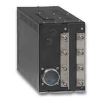
Honeywell KTA 870 System Installation Manual (253 pages)
MULTI-HAZARD AWARENESS SYSTEM/TRAFFIC ADVISORY SYSTEM
Brand:
Honeywell
| Category:
GPS
| Size: 4.19 MB
Table of Contents
List of Illustrations
8
Table of Contents
8
Figure 1-1 KMH 880/KTA 870 System
14
Table 1-1 KMH 880/KTA 870 Applicable Versions
14
Table 1-2 KMH 880 Lrus
14
Table 1-3 KTA 870 Lrus
14
Table 1-4 KMH 820 W/O GPS Multi-Hazard Unit Technical Specifications
14
Table 1-5 KMH 820 W/ GPS Multi-Hazard Unit Technical Specifications
14
Table 1-6 KTA 810 Traffic Advisory Unit Technical Specifications
14
Table 1-7 CM 805 Configuration Module Technical Specifications
14
Table 1-8 KA 815 Traffic Antenna Technical Specifications
14
Table 1-9 KA 92 GPS Antenna Technical Specifications
14
Table 1-12 KA 815/KA 92 Antennas
27
Table 1-21 Cable and Wire
31
Section II Installation
35
Figure 2-1 KMH 820/KTA 810 Installation Drawing
35
Figure 2-10 Bulkhead/In-Line Connection Coax Cable
35
Figure 2-11 TNC Antenna Coax/Connector Assembly
35
Introduction
37
Unpacking and Inspecting Equipment
37
Equipment Installation
37
General
37
Avionics Cooling Requirements
38
Processor Installation
38
Cooling Considerations
38
Installation Considerations
38
Installation Procedure
40
Configuration Module Installation
45
Cooling Considerations
45
Installation Considerations
45
Installation Procedure
45
Directional Antenna Installation
49
KA 815 Antenna Installation Considerations
49
KA 92 Antenna Installation Considerations (KMH 820 EGPWS Only)
53
Installation Procedure
53
TAS Coaxial Cable Fabrication
62
GPS Coaxial Cable Fabrication
63
GPS Antenna Splitter
63
Signal Losses
63
Figure 2-2 Configuration Module Installation Drawing
35
Figure 2-4 KA 815 Antenna Installation Drawing
35
Figure 2-5 KA 815 Doubler Plate Drawing
35
Figure 2-6 KA 92 Outline and Mounting Drawing
35
Figure 2-7 GPS Antenna Splitter
35
Figure 2-8 Coax Cable Treatment
35
Figure 2-9 Standard Coax Cable
35
Section III System Planning
67
Figure 3-1 KMH 880/KTA 870 Interconnect Family
67
Figure 3-2 KMH 820/KTA 810 Pinout Diagram
67
Figure 3-3 KMH 820/KTA 810 System Interconnect Block Diagram
67
Figure 3-4 KMH 820/KTA 810 Power Interface
67
Figure 3-5 KMH 820/KTA 810 Discrete Interface
67
Figure 3-6 KMH 820/KTA 810 Configuration Module Interconnect
67
Figure 3-7 KMH 820/KTA 810 Attitude/Heading Interface
67
Figure 3-8 KMH 820/KTA 810 Radar/Barometric Altitude Interface
67
Figure 3-10 KMH 820/KTA 810 EFS 40/50 Interface
68
Figure 3-11 KMH 820/KTA 810 GS 362A Interface
68
Figure 3-12 KMH 820/KTA 810 Honeywell GS 362A Interface
68
Figure 3-13 KMH 820/KTA 810 Collins GS 362A Interface
68
Figure 3-14 KMH 820/KTA 810 Honeywell Primus 1000 Interface
68
Figure 3-15 KMH 820/KTA 810 Honeywell SPZ-805 Interface
68
Figure 3-16 KMH 820/KTA 810 Diagnostic/Data Recorder Interface
68
Figure 3-17 KMH 820/KTA 810 TAS ATE Interface
68
Figure 3-18 KMH 820/KTA 810 CP 66B Interface
68
Figure 3-9 KMH 820/KTA 810 Antenna/Suppression Interface
68
Applicable Part Numbers Subsection Description
69
Electrical Characteristics Subsection Description
69
Function Subsection Description
69
Interface Subsection Description
69
Introduction
69
Requirements and Limitations Subsection Description
69
Air/Ground Discrete Input
73
General Interconnect Information
73
Power Inputs
73
Above/Below/Normal Input
74
Landing Gear Discrete Input
74
Advisory Inhibit Input
75
Baro Altitude (ARINC 429) Input
75
TAS Valid Output
75
Synthesized Voice Output
76
Visual Annunciate Traffic (Lamp Output)
76
Air Temperature Input
77
GPS Input
77
Factory Test Input
78
TAS ATE Enable Input
78
TAS Built in Test Equipment (BITE)
78
EGPWS Self Test Input
79
Display Select Input
80
Terrain Awareness Inhibit Discrete
80
Terrain Caution
80
Terrain Warning
80
Weather Select Output
80
EGPWS Audio on Discrete
81
EGPWS Terrain Inop and Terrain Not Available Output
81
Section IV Post Installation Configuration and Check out
169
Aircraft Configuration
171
Configuration Procedure
171
Introduction
171
Power on
171
Configuration Module Programming
172
Configuration String Format
172
Equipment Needed
172
Configuration Sequence of Events
174
Configuration Types
174
Category 1, Aircraft/Mode Type Select
176
Configuration Tables
176
Category 2, Air Data Input Select
177
Category 3, Position Input Select
177
Category 4, Terrain Display Select
178
Category 5, Input/Output Discrete Type Select
179
Category 8, Altitude Monitor Options
181
Category 9, Terrain Display Alternate Pop up Option
181
TAS Configuration Options
182
Ground Test Procedures
185
TAS RS-232 Maintenance Port
185
TAS RS-422 Data Recorder
185
EGPWS Ground Test Procedures
186
Section V Certification
207
Certification
209
Certification Procedure
209
Equipment Compatibility
209
Equipment Location
209
Introduction
209
FAA Form 337
210
FAA Requirements
210
Federal Communication Commission Rules
210
FTZ Requirement
210
TSO Category
210
Flight Manual Revision
211
Pilot Briefing
211
This Page Is Reserved
232
1 Introduction
233
2 Computer Requirements
234
3 Installing the TAS Diag Program
234
4 Starting TAS Diag
234
TAS Diag Demonstration Mode
236
5 Inspecting Current Processor I/O Data
236
Snapshot View
236
Continous View
237
6 Inspecting TAS Unit's Internal Diagnostic and Log Data
237
7 Configuration Module Options
238
View Strap Data
238
Modify Strap Data
239
Save to Text File
240
Save to Binary File
240
Copy from Binary File
240
Initialize Config Module
241
8 Intruder Data
242
Overwrite View
243
Capture View
243
9 Viewing Cable Calibration Data
244
10 Viewing Current System Status
245
11 TAS S/W Info
246
12 Ramp Tester Mode
246
Advertisement
Related Products
Honeywell KMH 880
Honeywell Bendix/King KTA970
Honeywell BendixKing KT 76C
Honeywell KT 74
Honeywell KTR 2280A
Honeywell KT73
Honeywell BENDIX/KING KTR 2280
Honeywell KaltecSoft Evolution KS20S-85
Honeywell BENDIX/KING KDF 806
Honeywell Kromschroder GIK 150F
Honeywell Categories
Thermostat
Controller
Control Unit
Security Camera
Accessories
More Honeywell Manuals
Login
Sign In
OR
Sign in with Facebook
Sign in with Google
Upload manual
Upload from disk
Upload from URL