Sign In
Upload
Manuals
Brands
Honeywell Manuals
Network Hardware
4909 CPVC
Honeywell 4909 CPVC Manuals
Manuals and User Guides for Honeywell 4909 CPVC. We have
1
Honeywell 4909 CPVC manual available for free PDF download: Operation Manual
Honeywell 4909 CPVC Operation Manual (34 pages)
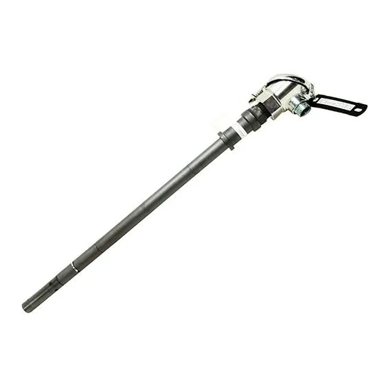
Conductivity Cell Removal/Insertion Assembly
Brand:
Honeywell
| Category:
Network Hardware
| Size: 0.18 MB
Table of Contents
About this Document
3
Table of Contents
5
1 Introduction
9
Overview
9
4908 Conductivity Cell
9
31074357 Removal Device
10
Figure 1-1 Temperature/Pressure* Range
10
Figure 1-3 4909 CPVC Conductivity Cell Insertion/Removal Assembly with Universal Head
11
Figure 1-4 4908 Conductivity Cell
12
Figure 1-5 31074357 Removal Device
12
Figure 1-6 Universal Head
13
2 Specifications and Model Selection Guide
15
Specifications
15
Cell Constants
15
Electrode Material
15
Wetted Parts
15
Pressure and Temperature (See Fig. 1-1)
15
Maximum Pressure
15
Mounting
15
Purge Port
15
Insertion Depth
15
Integral Automatic Temperature Compensation
16
Leadwire
16
Weight
16
Model Selection Guide
16
3 Installation
19
Requirements
19
Location and Position
19
Considerations
19
Prepare Assembly
20
Initial Prep
20
Mounting into the Process
20
Insertion
21
Removal
22
Electrical Connections
22
Figure 3-1 Outline and Dimension Drawing for 4909-X-X-X-X-03-X-X Conductivity Cell, Insertion Type with CPVC Removal Device
23
Figure 3-2 Outline and Dimension Drawing for 4909-X-X-X-X1-03-X-X Conductivity Cell, Insertion Type with CPVC Removal Device and Universal Head
24
4 Maintenance and Replacement Parts
25
To Clean the Cell
25
Replacing Removal Device Parts
25
Ball Valve
25
Nipples
25
Bushing and Washer
25
Replacement Parts
26
Table 4-1 Replacement Parts
26
Table 4-2 Voltage and Time Limits for Platinizing Cells
26
5 Platinization and Platinum Black
27
Figure 5-1 Installation Diagram-Cat. 4909 Cells with Junction Box Head Connected to 7082
28
Conductivity/Resistivity Analyzer
28
Figure 5-2 Installation Diagram-Cat. 4909 Cells with Junction Box Head Connected to 9782
29
Conductivity/Resistivity Analyzer
29
Conductivity/Resistivity Analyzer
30
Figure 5-3 Installation Diagram-Cat. 4909 Cells with 7 or 20 Foot Leads Connected to 7082
30
Figure 5-4 Installation Diagram-Cat. 4909 Cells with 7 or 20 Foot Leads Connected to 9782
31
Conductivity/Resistivity Analyzer
31
Advertisement
Advertisement
Related Products
Honeywell 4905 Style
Honeywell 4905
Honeywell 4600g
Honeywell 4600r
Honeywell 4600GHD051C-0F00E
Honeywell 4600GSF051C
Honeywell OMNI 408EU
Honeywell Ecomax 4P
Honeywell 450 3000
Honeywell 450 3001
Honeywell Categories
Thermostat
Controller
Control Unit
Security Camera
Accessories
More Honeywell Manuals
Login
Sign In
OR
Sign in with Facebook
Sign in with Google
Upload manual
Upload from disk
Upload from URL