Sign In
Upload
Manuals
Brands
Hewlett Packard Manuals
Medical Equipment
M1790A
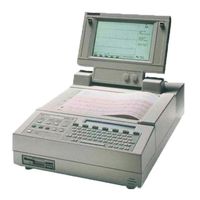
Hewlett Packard M1790A Cardiograph Manuals
Manuals and User Guides for Hewlett Packard M1790A Cardiograph. We have
1
Hewlett Packard M1790A Cardiograph manual available for free PDF download: Service Manual
HP M1790A Service Manual (277 pages)
Cardiographs, Mobile Cart, Telecommunications Package
Brand:
HP
| Category:
Medical Equipment
| Size: 11.53 MB
Table of Contents
Table of Contents
7
Pagewriters with Serial Number Prefix Prior to 3208A
12
1 Introduction
18
Pagewriter XL Cardiographs
18
M1700A Pagewriter Xli Cardiograph with Preview Display
19
M1705A Cart
20
M1706A/B Telecommunications Package
21
A.02.XX Software
21
Inquiries
21
Specification Data
22
Patient Module Specifications
22
SAECG Patient Module Specifications
23
Power Supply and Battery Specifications
24
Options and Accessories
26
Pagewriter Xli, Xls and Xle Cardiographs
26
Country Options
26
Delete Options
26
Cable Options
26
Supplies/Accessories Options
27
Substitute Options
27
Documentation Options
27
Standard Accessories Supplied
27
M1703A Pagewriter Xli Upgrade Kits
28
Options
28
M1704A Pagewriter Xls Upgrade Kits
28
M1706A Telecommunications Package
28
Options
29
M1753A Pagewriter Xle Upgrade Kit
29
System
29
Documentation Options
29
M1755A Pagewriter Xli Upgrade Kit
29
M1756A Pagewriter Xli Direct Digital ECG Fax Modems
30
Options
30
M1788A Extra Patient Module
30
Substitute Options
30
M1790A Pagewriter Xli Vectorcardiography
31
Country Option Configurations
31
2 Installation and Configuration
32
Installation
32
Installing the M1756A Fax Modem
33
Printing an ECG on an HP Laserjet Printer
35
Setting up the Laserjet Printer
36
Configuring the Cardiograph to Print Ecgs on the HP Laserjet
37
Connecting the Patient Module
38
Changing the Line Voltage Setting
39
Changing the Line Fuses
40
Installing the Battery
42
Fitting the Battery Holder Tab into the Battery Slot
43
Loading the Paper
45
Loading the Paper
46
Configuration
48
Configuring the M1702A
49
Selecting Configuration Parameters
50
Global Configuration
51
Interpretation Parameters
55
Power-On Application (M1755A A.02.X); and Higher Software Only)
55
Line Frequency
55
Custom Lead Groups
56
Autocopy
56
ECG Management Parameters
57
Battery Timeout
57
Password
57
ID Configuration
58
Transmit Configuration
59
Transmit
59
Entering the Phone Number
60
Receive
61
Autodial
61
Configuration Files
62
Store
62
Laserjet Printer Configuration
62
Print
63
3 Operation
64
The Keyboard and Front Panel
65
Choosing a Report Format
67
An Auto 3X4 ECG (3X4)
69
An Auto 3X4 ECG with Three Rhythm Strips (3X4, 3R)
70
A Manual 6-Lead ECG
71
An SAECG Report
72
Main Functions
73
Transmit (M1700A Only)
74
Store (M1700A & M1701A Only)
75
Config
75
Checkdisk (M1700A & M1701A Only)
75
A.02.XX and Higher Software
75
Files (M1700A & M1701A Only)
76
The Selection Display (M1700A & M1701A Only)
78
Selection Display Menu, Part 1
78
Selection Display Menu, Part 2
78
Recording an ECG
79
Using the Patient Module Start Button
80
Preview Plus (A.02.XX and Higher Software Only)
80
Using Preview Plus
80
4 Performance Verification and Maintenance Introduction
82
Performance Verification
82
Visual Inspection
82
Extended Self-Test
83
Patient Module and Cable Test
84
CPU Assembly Test
84
Printer Test
85
Disk Drive Test (M1700A and M1701A Only)
85
Preview Display Test (M1700A Only)
86
Keyboard Display Test
87
Modem Test (M1700A Only)
87
All Tests
88
Printing the Error Log
88
ECG Simulation
89
Preventive Maintenance
90
Care and Cleaning
91
Cleaning the Cardiograph and Patient Module
91
Cleaning the Keyboard
91
Cleaning the Printhead and Paper Sensor
92
Maintaining the Flexible Disk Drive
93
Cleaning the Electrodes, Leadwires, and Patient Data Cable
94
Safety Tests
94
Pagewriter XL Performance Verification Checklist
95
Visual Inspection
95
Extended Self-Test
95
ECG Simulation
96
Comments
96
5 Theory of Operation
97
Operational Overview
97
ECG Data Path
97
Power-On
98
Power-Off
98
Circuit Descriptions
100
The Standard Patient Module
102
Patient Module Block Diagram
103
CPU Assembly
104
Cpu
104
System Memory
104
CPU Assembly Block Diagram
105
Rom
106
I/O Control
108
The FGA
108
I/O Control Block Diagram
109
Serial Communications
110
Digital Signal Processor
110
Serial Communications Circuitry
110
System Expansion Connector
111
Disk Drive (M1700A and M1701A Only)
111
Power Supply
112
VMAIN and VIN
112
Battery Charger and Battery Sensor
112
Battery Operation and Condition
114
Volt Regulator
115
Overvoltage/Undervoltage Sensor
115
Printer Switch
116
Battery Switch
116
ACON Detector
116
Backup Supply and Low Battery Disconnect
117
To Backup Switchover
117
Patient Module Voltage Regulator
117
The Keyboard and Keyboard Display
118
Printer
118
Printer Gate Array
118
Printer RAM
118
Motor Driver
118
ADC (Analog-To-Digital Converter)
119
Thermal Printhead
119
The Preview Display
120
Preview Logic Board
120
Preview Logic Board Block Diagram
121
Preview Display Power Supply Board
122
VLCD Supply
123
VCFL Supply
123
Preview Screen
123
Preview Display Power Supply Block Diagram
123
6 Troubleshooting
124
Introduction
124
Maintenance Philosophy
124
Test Equipment
124
The Error Log
125
Clearing the Log
125
Errors
126
Using Extended Self-Test in Troubleshooting
127
Troubleshooting Tables
128
Power-On Errors
131
Power Supply and Battery
132
Patient Module and Patient Data Cable
135
Preview Display and Logic (M1700A)
142
Transmit and Modem
144
Testing the Power Supply
145
Voltage Test Locations
147
7 Removal and Replacement
148
Introduction
148
Tool Requirements
149
The Battery
149
Removing the Battery
149
Replacing the Battery
151
Fitting the Battery Holder Tab into the Battery Slot
151
The Keyboard
152
The User Interface Assembly
152
Removing the User Interface Assembly
152
Replacing the User Interface Assembly
153
The Printer Drive Assembly
154
Removing the Printer Drive Assembly
154
Pagewriters with Serial Number Prefix 3208A or Later
154
Removing the Printhead Cover
154
Pagewriters with Serial Number Prefix Prior to 3208A
156
Removing the Printhead Cover
156
Printer Drive and Keyboard Ground Plane Screw Locations
157
Replacing the Printer Drive Assembly
158
The Preview Screen Assembly
159
Removing the Preview Screen Assembly
159
Pagewriters with Serial Number Prefix 3208A or Later
159
Removing the Entire Preview Screen Assembly
159
Disassembling the Preview Screen Assembly
160
Opening and Removing the Top Cover Assembly
160
Pagewriters with Serial Number Prefix Prior to 3208A
162
Removing the Entire Preview Screen Assembly
162
Disassembling the Preview Screen Assembly
162
Removing the Preview Screen Assembly
163
Replacing the Preview Screen Assembly
164
The Top Cover Assembly
164
Opening and Removing the Top Cover Assembly
164
Opening and Removing the Top Cover Assembly
166
Pagewriters with Serial Number Prefix 3208A or Later
167
The Printhead Assembly
167
Pagewriters with Serial Number Prefix Prior to 3208A
168
Removing the Printhead Cover and Printhead
169
Removing the Optical Paper Sensor
170
Printhead Resistance Codes
170
Printhead Resistance Selector
171
The Preview Logic Board
172
Removing the Preview Logic Board
172
Pagewriters with Serial Number Prefix 3208A or Later
172
Preview Logic Board Removal (Serial Number Prefix 3208A or Later)
173
Pagewriters with Serial Number Prefix Prior to 3208A
174
Replacing the Preview Logic Board
175
The CPU Assembly
176
Removing the CPU Assembly
176
Screw and Connector Locations on the CPU Assembly
177
Replacing the CPU Assembly
178
The Disk Drive (M1700A and M1701A Only)
178
8 Parts Lists
180
Introduction
180
Ordering Information
180
Calling for Assistance
180
United States of America
180
Canada
180
Patient Module Diagram
181
Fastener List
193
Preview Display Assembly Diagram
196
Cart Exploded Diagram
198
Cart Parts List
199
Direct Connect Cable Parts List
203
Cabling for Hayes Modem and Direct Connect
205
Hayes Modem and Direct Connect Cables Parts List
205
CPU Assembly Connectors
207
Preview Display Connectors
217
Introduction
219
Installation and Configuration
220
Connecting the Patient Module
220
Installing the SAECG Software
221
SAECG Configuration (A.02.XX and Higher Software Only)
222
Acquisition Fields
222
Measurement Fields
223
Operation
224
SAECG (M1754A Only)
228
Editing and Printing a Stored SAECG
228
Performance Verification and Maintenance
229
Extended Self-Test
229
Patient Module and Cable Test
230
Theory of Operation
231
The SAECG Patient Module
231
Troubleshooting
233
Parts List
234
Introduction
235
Installation and Configuration
236
Operation
237
Transmitting Ecgs by Fax
237
Transmitting more than One ECG
238
Receiving Ecgs
238
Performance Verification and Maintenance
239
Extended Self-Test
239
Fax Modem Test (M1700A Only
240
Troubleshooting
241
Parts List
242
Installation and Configuration
246
Setting up the Patient Module
246
Software Installation
247
VCG Configuration (A.03.XX Software Only)
247
Disabling VCG Reports
248
Operation
248
Recording a VCG
248
Printing a Stored VCG
249
The VCG Report
250
VCG Report Formats
251
Formats
251
Troubleshooting
254
Parts List
256
Index
257
Advertisement
Advertisement
Related Products
Hewlett Packard M1756A
Hewlett Packard M1754A
HP M1772A
HP M2475B
HP M2480B
HP M2478A
HP M2479A
HP m1000 Series
HP LaserJet M112 Series
HP LaserJet M112a
Hewlett Packard Categories
Desktop
Laptop
Server
Monitor
Switch
More Hewlett Packard Manuals
Login
Sign In
OR
Sign in with Facebook
Sign in with Google
Upload manual
Upload from disk
Upload from URL