Sign In
Upload
Manuals
Brands
GE Manuals
Industrial Equipment
Mark VIeS
GE Mark VIeS Manuals
Manuals and User Guides for GE Mark VIeS. We have
2
GE Mark VIeS manuals available for free PDF download: System Manual
GE Mark VIeS System Manual (487 pages)
Functional Safety Systems for General Market
Brand:
GE
| Category:
Industrial Equipment
| Size: 6.73 MB
Table of Contents
Related Documents
3
Safety Symbol Legend
4
Control System Warnings
5
Table of Contents
6
1 Orderable Part Numbers
9
Module Part Numbers
10
Power Distribution Module and Daughterboard Part Numbers
12
Mark Vie and Mark Vies Controllers Part Numbers
13
Ionet Switch and DIN-Rail Mounting Clip Part Numbers
14
Mark Vie Power Supplies and OR-Ing Module Part Numbers
15
UCSC Controller Data Name Plate
17
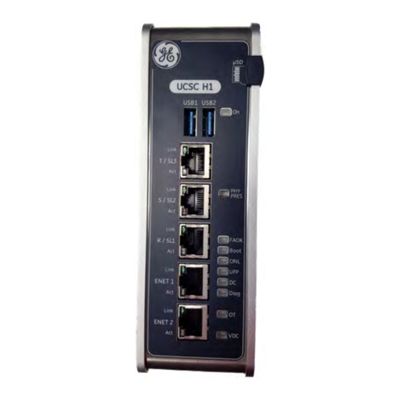
UCSC Controllers
17
Mark Vie UCSCH1B Controllers
18
UCSCH1 Platform Configuration Supported Features
18
Mark Vies Safety UCSCS2A Controller
19
Mark Vies UCSCS2A Controllers
19
UCSC Specifications
20
UCSC Mounting Requirements
21
UCSC Mounting Requirements to Achieve 70ºC Operating Temperature
22
UCSC Mounting Requirements to Achieve 65ºC Operating Temperature
23
UCSC Controller Mounting Dimensions
24
3-Pin Power Plug
25
Power Requirements
25
Interface Details
26
UCSC Connection Ports (Front View)
26
UCSC Connection Ports (Bottom View)
27
Mark Vie UCSCH1B Ethernet Ports
28
Mark Vies UCSCS2A Ethernet Ports
28
To Change the UDH Network IP Address for the UCSC
29
To Set the Controller’s Network Address Using the COM Port
29
UCSC Operation
29
UDH Network Configuration
29
Act LED
30
Leds
30
Link LED
30
On LED
30
Over-Temperature Protection
31
UCSC COM Port
31
UCSC Embedded Field Agent (EFA)
31
UCSC Virtual Network
32
Agency Certifications and Standards
33
Accessories
34
To Replace the UCSC with Another UCSC
35
UCSC Hardware Replacement
35
To Perform UCSC Restore
36
UCSC Restore
36
Black Channel Safety Communication
37
Controller Password Protection
37
Controller Setup and Download
37
Shared Ionet
37
Initial Download to I/O Modules
38
Prerequisites
38
To Update Terminal Boards Online
38
Update Terminal Boards
38
Controller Diagnostic Alarms
40
Description Diagnostic Alarm Reset
40
Toolboxst Application Detects a Diagnostic Status Signal
41
Application Runtime Error
44
Control/Status Communication Error
44
Could Not Determine Platform Type from Hardware
45
Firmware Error - Internal Process Crashed
46
Platform Hardware Does Not Match Configuration
46
Application Code Load Failure
47
Application Error - Application Overrunning the Frame
47
Controller CPU Overtemperature
47
Configuration Load Error
48
EGD Error - Fault Tolerant EGD Activated
48
Internal Runtime Error - Process Alarms Not Being Scanned
48
Process Alarm Buffers Full - Controller Can Miss Alarm Transitions
48
Communication Lost from R Processor
49
EGD Error - Fault Tolerant EGD Data Requested
49
Communication Lost from S Processor
50
Communication Lost from T Processor
50
Startup Sequence Failed
51
Frame Skips Detected
52
Overtemperature
52
Controller Is Unlocked
53
Memory Verification Failed – Firmware Processes
53
Output Exchange Disagreement Detected
53
Running Application Does Not Match the Branded Application
53
Intermittent Communications on Ionet1
54
Intermittent Communications on Ionet2
54
Intermittent Communications on Ionet3
54
Memory Validation Failed
55
Nans Detected in CALC or NAN_BREAKER Block
55
State Exchange Voter Disagreement Detected
55
Sequencer Client Execution Overrun
56
Sequencer Client Execution Underrun
56
Sequencer Frame Period Out-Of-Bounds
56
Sequencer Out-Of-Order or Overrun Detected
56
Description too Many State Voter Disagreements Detected
57
Sequencer Data Structures
57
Sequencer Frame Number Skip Detected
57
Sequencer Frame State Timeout Out-Of-Bounds
57
Controller Has Entered Quality Control (QC) Mode
58
Could Not Create the Command and Event Log (CEL) File
58
Hardware Reconfigured: Reboot by Removing and Reapplying Power
58
Invalid Calibration Settings
58
UDH EGD Fault Detected by the R Processor
60
UDH EGD Fault Detected by the S Processor
60
UDH EGD Fault Detected by the T Processor
60
Auto-Reconfiguration Server Failed Scanning or Downloading an I/O Pack
61
Auto-Reconfiguration Server Installation Is Incomplete
61
Could Not Configure Consumed Exchanges from One or more Producers
61
EGD Error - One or more Consumed Exchanges Contain Unbound Variables
62
Hardware Watchdog Has Been Disabled
62
Software Watchdog Has Been Disabled
62
CDH EGD Fault Detected by the R Processor
63
CDH EGD Fault Detected by the S Processor
63
CDH EGD Fault Detected by the T Processor
64
Failed to Incorporate the User-Configured Frame State Timeouts
64
Fan Loss Detected for Controller Fan
64
Syspage Inconsistency Detected
65
Total Memory Consumption Has Exceeded
65
R Network Shared I/O Module Inputs Unhealthy
66
Unauthorized Executable was Detected and Terminated
66
S Network Shared I/O Module Inputs Unhealthy
67
T Network Shared I/O Module Inputs Unhealthy
67
Application Mismatch between Redundant Controllers
68
Controller Certificate Has Been Revoked
68
Controller Certificate will Expire Within 30 Days
68
Controller Certificate Has Expired
69
Controller Certificate will Expire in One Day
69
Controller Certificate will Expire Within Seven Days
69
Certificate Authority (CA) Certificate will Expire Within 30 Days
70
Certificate Authority (CA) Certificate will Expire Within One Day
70
Certificate Authority (CA) Certificate will Expire Within Seven Days
70
Controller to Controller (C2C) Inputs Unhealthy on Ionet
70
Certificate Revocation List (CRL) Has Expired
71
Communications Error with Certificate Authority Server
71
Default User Password Detected
72
Description Active PFFA Diagnostics Detected
72
Inputs Unhealthy on IO Module
74
Description Ethercat All Ethernet Links Disconnected
81
Description Ethercat Scan Bus Error
81
Ethercat Device Disconnected
82
Ethercat Device in Unexpected State
82
Ethercat Limit for Lost Frames Has Been Exceeded
82
Ethercat Linebreak Detected between Devices
82
Ethercat Configuration Is Not Supported
83
Ethercat ENI File Does Not Match Bus Configuration
83
Ethercat Redundant Ethernet Links Crossed
83
3 Unmanaged Ethernet Switches
85
Available Form Factors
86
Installation
86
Configuration
87
Ionet Switch Specifications
87
Operation
88
Conformance Criteria
88
Flow Control (Pause)
88
Reliability and Performance
88
Diagnostic Leds
89
Third-Party Switch Replacement
90
Holes to Support Panel Mounting
90
4 YAIC Analog I/O Modules
91
Mark Vies YAIC Analog I/O Pack
91
YAIC Compatibility
92
YAIC Version Compatibility
92
YAIC Terminal Board Compatibility
92
YAIC Installation
93
Connectors
93
YAIC Operation
94
Analog Input Hardware
94
Analog Output Hardware
95
YAIC Specification
96
YAIC Diagnostics
97
Status Leds
97
Relay Application Leds
97
YAICS1B Configuration
98
Parameters
98
Inputs
98
Outputs
99
Variables
100
YAIC Specific Alarms
101
Analog Input Unhealthy
101
Individual Current Feedback Unhealthy
101
Total Current Feedback Unhealthy
102
Internal Reference Current Unhealthy
102
Individual Current too High Relative to Total Current
102
Total Current Varies from Reference Current
103
Commanded Current Fdbk Error
103
Suicide Relay Non-Functional
103
Output 20/200 Ma Suicide Active
104
Suicide on Overcurrent, Check Terminal Board Jumper
104
I/O Pack Internal Power Supply Status Not OK
104
Dither Time Is Frozen or out of Range
104
I/O Pack Internal Reference Voltage out of Limits
105
I/O Pack Internal Null Voltage out of Limits
105
Logic Signal Voting Mismatch
105
TBAIS1C Analog Input/Output
106
Compatibility
106
TBAI Analog I/O Capacity
109
Board TBAI
110
Application Board
110
Terminal Board TBAI
111
TBAI Diagnostics
112
TBAI Jumper Configuration
112
STAIS2A Simplex Analog Input
113
5 YDIA Discrete Input Modules
115
Mark Vies YDIA Discrete Input Pack
115
YDIA Compatibility
116
YDIA Version Compatibility
116
YDIA Terminal Board Compatibility
116
Input Signals
117
Variable Threshold
117
Diagnostics
118
YDIA Status Leds
118
Discrete Input Leds
118
Configuration
119
YDIA Specific Alarms
120
Contact Input Not Responding to Self-Test Mode
120
Excitation Voltage Not Valid, Contact Inputs Not Valid
120
Contact Input Terminal Board
121
TBCIS#C Contact Input with Group Isolation
121
TBCI Installation
122
TBCIH4C Contact Input Circuits
125
TBCI Specifications
126
TBCI Diagnostics
126
STCIS#A Simplex Contact Input
127
STCI Compatibility
127
Wiring to STCI Terminal Board
128
STCI Specification
129
6 YDOA Discrete Output Modules
131
Mark Vies YDOA Discrete Output Pack
131
YDOA Compatibility
132
YDOA Version Compatibility
132
YDOA Terminal Board Compatibility
132
YDOA Installation
133
To Install the YDOA Pack
133
Relay Command Signals
134
Output Enable
134
Monitor Inputs/Control
134
YDOA Specification
135
YDOA Diagnostics
136
YDOA Status Leds
136
Output Leds
136
YDOA Configuration
137
YDOA Specific Alarms
138
Logic Signal
138
Relay Circuit
138
Terminal Board Fuses
139
All Fuses Blown or no Terminal Board Excitation
139
Relay Output Coil Does Not Match Commanded State
140
No Contact Voltage Disagreement with Command
140
Relay Driver Does Not Match Commanded State
140
Relay Connected Field Device Impedance Outside of Acceptable Range
141
Peer to Peer Communication Failure Code
141
Peer to Peer Communication Compatibility Mismatch: YDOA
141
TRLY Discrete Output Terminal Boards
142
TRLYS1B Relay Output with Coil Sensing
143
TRLYS1B Relay Output Terminal Board
143
TRLYS1B Compatibility
144
TRLYS1B Installation
144
TRLYS1B Terminal Board Wiring
145
TRLYS1B Operation with Multiple Power Sources
146
Dry Contacts
146
Simplex
147
TRLYS1B Circuits, Simplex System
147
Tmr
148
TRLYS1B Circuits, TMR
148
TRLYS1B Specifications
149
TRLYS1B Diagnostics
149
TRLYS1B Configuration
149
TRLYS1D Relay Output with Solenoid Integrity Sensing
150
TRLYS1D Block Diagram
150
TRLYS1D Compatibility
151
TRLYS1D Installation
151
TRLYS1D Terminal Board Wiring
151
TRLYS1D Operation
152
TRLYS1D Solenoid Fault Announcement
152
TRLYS1D Circuits (TMR)
153
TRLYS1D Specifications
154
TRLYS1D Diagnostics
154
TRLYS#F Relay Output - TMR Contact Voting
155
TRLYS#F Block Diagram
155
TRLYS#F Compatibility
156
TRLYS#F Installation
156
TRLYS1F Terminal Board Wiring
157
TRLYS#F Operation
158
TRLYS1F Contact Arrangement for TMR Voting
158
TRLYS#F Specifications
159
Derating Voted Relay Contact Output Diagram
159
TRLYS#F Diagnostics
160
SRLYS2A Simplex Relay Output
161
SRLY Compatibility
161
SRLY Terminal Board Layout
162
Function of each Terminal Point as Related to an Option Board
163
Srlys2A
164
Srly + Wrob
164
SRLYS2A + WROB Circuitry
165
SRLY + WROF Fused in Series
166
SRLY + WROF Isolated Contact Voltage Feedback
166
Fused in Series
166
Normally Open
167
Normally Closed
167
Srly + Wrog
168
SRLYS2A + WROG Circuitry
168
SRLY Specification
169
7 YUAA Universal I/O Modules
171
Mark Vies YUAA Universal I/O Pack
171
Support for Universal I/O Modules in Controlst
171
YUAA Specifications
172
YUAA Ma/Hart Specifications
173
YUAA Performance
174
YUAA Orderable Part Numbers
175
Module Installation and Mounting
176
To Install the YUAA Module into an Existing Control Cabinet
176
Mounting Dimensions
177
YUAA DIN-Rail Installation and Removal
178
Wiring and Configuration
179
Wiring and Configuration for New Installs
179
Wiring and Configuration for STAI or SHRA Retrofits
180
Wiring and Configuration for STAO Retrofits
181
Wiring and Configuration for STTC Retrofits
182
Wiring and Configuration for SRTD Retrofits
183
Wiring and Configuration for 24 V STCI Retrofits
184
YUAA Channel Organization
186
Operation
186
Analog Inputs Wiring Options
188
Analog Inputs (Voltage or Ma Current)
188
GEH-6855_Vol_Ii Mark Vies Functional Safety Systems Volume II
188
Current Outputs
189
0–20 Ma Analog Current Outputs
189
HART-Enabled Ma Inputs and Outputs
190
RTD Inputs
191
RTD Wiring
191
RTD Types and Temperature Ranges
191
Thermocouple Inputs
192
Supported TC Types and Temperature Ranges
192
Cold Junctions
193
Digital Inputs and Outputs
194
NAMUR Style Sensor Inputs
194
External Wetted Contact Inputs
196
External Wetted Contact Inputs with 10 to 20 V Field Supply
196
Internal Wetted Contact Inputs
198
Internal Wetted Contact with Line Monitoring Wire Detection
198
Discrete Output Using Ma Outputs and Interposing Relays
199
Pulse Accumulator
200
Wiring Details for Pulse Accumulator Inputs
200
Configuration
200
Configuration (Modes)
201
Current Inputs
202
Voltage Inputs
205
Rtds
205
Thermocouples
205
Pulse Accumulators
207
Pulse Accumulator Buffer Example
208
Frequency Calculation Example
209
HART Signal Definitions
211
HART Extended Status
212
I/O Point Health Status
213
I/O Status Leds
213
For Digital Inputs
213
For Ma Outputs
213
Diagnostics
213
Other Diagnostic Monitors
214
Replace YUAA I/O Pack with Another YUAA I/O Pack
214
Replacement
214
Replace SUAA Terminal Board
215
Replace Existing Mark Vies I/O Module with YUAA I/O Module
215
To Replace the SUAA Terminal Board
215
YUAA Diagnostic Alarms
216
Failed Loading Configuration for Point
216
Point Unhealthy Troubleshooting
216
Cold Junction Temp
218
Current Output Commanded Current Feedback Error
219
Open Field Wire Detected
219
Thermocouple Input Millivolt Exceeds Hardware Limit
219
Thermocouple Value Beyond Range of Configured TC Type
220
RTD Voltage out of Range
220
RTD Current out of Range
220
RTD Resistance Beyond Range of Configured RTD Type
221
HART Not Initialized
221
HART Address Mismatch
221
HART Field Device Modified
221
HART Extended Status Mismatch
222
HART Control Messages Disabled
222
Coldjunction Temperature
222
Internal Burden Resistor Protection Activated
222
Shorted Field Wire Detected
223
NAMUR Sensor Failure Detected
223
Input Saturation Detected
223
HART Field Device Not Write Protected in Locked Mode
224
Outputs Are Disabled
224
Cold Junction Sensor
224
Cold Junction Difference Detected
224
SUAA Universal Analog Terminal Board
225
SUAA Terminal Board Screw Definitions
225
8 YVIB Vibration Monitor Modules
227
Mechanical Vibration Standards
227
Index for Application Diagrams
227
Mark Vies YVIB Vibration Monitor I/O Pack
228
YVIB Compatibility
229
YVIB Version Compatibility
229
YVIB Terminal Board Compatibility
229
YVIB Specifications
230
YVIB Supported Sensor Inputs
230
YVIB Installation
231
To Install a New YVIB Module into an Existing Control Cabinet
231
YVIB I/O Pack Replacement
232
To Replace a YVIB I/O Pack
232
YVIB I/O Pack Replacement Use Cases
232
To Upgrade YVIB Hardware Forms
233
Gap 9–12 before Upgrade (Example)
233
Gap 9–11 and KPH Tabs after Upgrade before Correction (Example)
233
KPH Tab after Upgrade after Correction (Example)
233
YVIB Functions
234
Vibration Monitoring Hardware
234
Accuracy of Vibration Inputs
235
Accuracy of Vibration Inputs for YVIBS1B
235
Accuracy of Position Inputs
235
Accuracy of Position Inputs for YVIBS1B
235
Tracking Filters
236
Wideband Filters & Velocity Conditioning
236
CDM Sensors
236
Vibration Monitoring Firmware
236
Signal Space Inputs for Sensor Types, with Firmware Version 5.0
237
System Limits
237
Configuration of System Limits
238
System Limits Implementation
238
Legacy Peak-Peak Algorithm
238
Enhanced Peak-Peak Algorithm
239
Enhanced RMS Algorithm
239
Default Sensor Gain and Bias
240
Sensor Gain and Bias Override
241
Use of Gain and Snsr_Offset in YVIB
241
Maximum Input Voltage Definition
241
Minimum Input Voltage Definition
241
Input Clipping Due to Gain
242
YVIB Firmware Changes
243
YVIBS1B Firmware Enhancements
243
Vibration Monitoring Application Examples
243
Input Processing
243
Position Configuration
244
Position Application Example
244
Example Proximitor Specifications
244
To Configure GAP9_POS1
245
Keyphasor
246
Keyphasor Input Processing
246
Gapn_Kph# Signal Path (Keyphasor)
246
Keyphasor Configuration
247
Keyphasor Application Example
247
Keyphasor Sensor Monitoring Pedestal Key
247
Example Keyphasor Specifications
247
To Configure GAP13_KPH1
248
Vibration Displacement
249
Vibration Displacement Input Processing
249
Wideband Vibration Scan Period
249
Vibration Displacement Configuration
250
Gapn_Vibn
250
Tmr_Difflimt
250
Vibn
250
Vibration Displacement Application Example
251
Vibration Displacement Sensor
251
To Configure GAP4_VIB4
252
Velocity
252
Velocity Input Processing
252
Velocity Input Configuration
254
Velocity Application Example
255
Example Velomitor Specifications
255
Combustion Dynamics Monitoring
257
CDM Input Processing
257
CDM Configuration
258
CDM Application Example
260
Example PCB Sensor Specifications
260
To Configure Channel 1
260
Component Editor
262
Probe Nominal Settings
263
Lm 1–3
264
Vib1X 1-8
264
Vib2X 1-8
264
Vib 1-8
265
Gap 1-3
266
Gap 4-8
267
Gap 9-11
268
Kph
269
YVIB Diagnostics
270
YVIB Specific Diagnostic Alarms
271
A/D Converter Calibration Failure
271
D/A Converter Calibration Failure
271
Initialization Error Detected
271
Internal Data Transfer Error
272
Internal Hardware Failure
272
DC Isolation Test Failure
272
I/O Pack Processor Failure
272
Negative 28 Volt Power Low
273
Dual Ethernets Not Supported with 10 Ms Frame Rate
273
Pack Internal Reference Voltage out of Limits
273
Internal Daughterboard Temperature Limit Exceeded
273
Channels 1, 5, 9, 13 ADC Failure
274
Channels 2,6,10 ADC Failure
274
1X2X Phase Calibration Level
274
Current Operating Mode Is Incompatible with this Hardware
274
Sensor Type Is Not Supported with this Hardware
275
Voting Mismatch
275
TVBA Vibration Input
276
TVBA Compatibility and Attributes
276
TVBA Installation, Operation, and Jumper Configuration
276
Accelerometers with Integrated Outputs
276
Seismic Sensors
277
I/O Variable Name, Vibx
277
Velomitor Sensors
278
Eddy-Current or Proximitor Sensors for Position and Velocity
278
Eddy-Current or Proximitor Sensors for Keyphasor
279
Bently Nevada 350500 Charge Amplifier
280
PCB Piezotronics 682A02 Signal Conditioner
280
Customer Terminal Points
281
TVBAS2B Buffered Outputs
282
Bently Nevada Buffered DB Connector Points
282
Jumper, Jpxb
282
TVBA Specifications
283
9 PSCA Modbus Master (Serial Communication) Module
285
PSCA Serial Communication I/O Pack
285
To Install the PSCA I/O Pack
286
Serial Channels
286
Dataflow from PSCA to Controller
287
Serial Modbus Master Service
288
Ethernet Modbus Master Service
289
PSCA Specification
290
PSCA Specific Alarms
291
Communication Failure - Bad Data
292
Configuration Problem Port
292
Electric Drive Port
292
SSCA Simplex Serial Communication Input/Output
293
SSCA Jumper Positions
293
Signal Assignments
294
Terminal Board Screw Connections
294
Termination Jumpers
294
Ground Jumpers
295
SSCA Specification
295
SSCA Configuration
296
RS-232C (Point-To-Point)
296
RS-232C to Third-Party Device
297
RS-485 Half-Duplex to Third-Party Device (Slave)
299
RS-485 (Half-Duplex) – Point-To-Point
300
RS-485 (Half-Duplex) – Multidrop
300
10 PDM Power Distribution Modules
301
Power Distribution Overview
301
Core Components
301
PPDA Status Feedback
302
Valid PDM Core Board Combinations
302
Branch Circuit Boards
302
Circuit Protection
303
P28 Control Power Protection
303
P28 System Monitoring
303
P28 Branch Circuit Protection
304
125 V DC Power Protection
304
125 V DC Branch Circuit Protection
304
24/48 V DC Power Protection
305
PPDA Power Distribution System Feedback
306
Signal Input
307
DC-62 Power Diagnostic Pin Assignments
307
PPDA LED Control
308
Using the LED Number as a Reference
309
To Install the PPDA I/O Pack
310
Signal Routing
311
PPDA Basic Signal Routing Example
311
PPDA Specification
312
Power Distribution Leds
313
Jpdg
314
JPDS Inputs
315
Ps28Venable
315
JPDS Contact/Fuse
316
JPDG Inputs
316
JPDG Fuse/Dry Contacts
317
JPDE Input
317
JPDE Gnd Volts
317
JPDE Fuse
318
PPDA Specific Alarms
319
P28V-S Volt Fdbk (JS/PS Connector) out of Range
319
P28V-T Volt Fdbk (JT/PT Connector) out of Range
320
P28V-R Contact Input (JR Connector) Indicates PS Problem
320
P28V-S Contact Input (JS Connector) Indicates PS Problem
321
P28V-T Contact Input (JT Connector) Indicates PS Problem
321
P28V-R Aux Output Fuse (JAR Connector) Not OK
322
P28V-S Aux Output Fuse (JAS Connector) Not OK
322
P28V-T Aux Output Fuse (JAT Connector) Not OK
322
P28V-R Volt Fdbk (JR/PR Connector) out of Range
323
Description JPDM- Fuse FU4 (J1 Connector) Is Blown
327
Description JPDM- Fuse FU5 (J1 Connector) Is Blown
327
Description JPDM- Fuse FU6 (J1 Connector) Is Blown
327
Description JPDM- Fuse FU7 (J2 Connector) Is Blown
328
Description JPDM- Fuse FU8 (J2 Connector) Is Blown
328
Description JPDM- Fuse FU9 (J2 Connector) Is Blown
328
JPDF DC 125V Ground Magnitude (JD1/JZ2/JZ3 Connector) out of Range
333
JPDF Fuse FU1R or FU2R (J1R Connector) Is Blown or SW1R Switched off
333
PPDA Invalid Combination: more than 2 JPDM Boards Present
340
PPDA Invalid Combination: both JPDS and JPDM Terminal Boards Present
340
JPDE 24/48 VDC Magnitude (JD1/JPS1/JPS2 Connector) out of Range
340
JPDC-DC 125V Gnd Fdbk Mag (JD1/JZ2 Connector) out of Range
346
JPDC-Fuse FU71 or FU72 (J7A Connector) Is Blown or SW7A Switched off
346
JPDC-Fuse FU1R or FU2R (J1R Connector) Is Blown or SW1R Switched off
348
JPDC-Fuse FU1S or FU2S (J1S Connector) Is Blown or SW1S Switched off
348
JPDC-Fuse FU1T or FU2T (J1T Connector) Is Blown or SW1T Switched off
349
Input Src Mismatch on JPDC: AC Src Detected at Input Instead DC
349
JPDC-AC [ ]V Fdbk (JAC Connector) out of Range
350
JPDC-Fuse FUAC1 (JAC1 Connector) Is Blown or SWAC1 Switched off
350
JPDC-Fuse FUAC2 (JAC2 Connector) Is Blown
351
JPDC-P28V-R Volt Fdbk (JR/PR Connector) out of Range
351
JPDC-P28V-S Volt Fdbk (JS/PS Connector) out of Range
352
JPDC-P28V-T Volt Fdbk (JT/PT Connector) out of Range
352
JPDC-P28V-R Contact Input (JR Connector) Indicates PS Problem
353
JPDC-P28V-S Contact Input (JS Connector) Indicates PS Problem
353
JPDC-P28V-T Contact Input (JT Connector) Indicates PS Problem
354
PPDA Invalid Combination: more than 1 JPDC Board Present
354
PPDA Invalid Combination: JPDC and JPDS Boards Present Together
354
PPDA Invalid Combination: more than One JPDF Connected to JPDC Board
355
PPDA Invalid Combination: more than One JPDB Connected to JPDC Board
355
PPDA Invalid Combination: JPDC and JPDM Boards Present Together
355
JPDG-P28V Volt Fdbk (JR/JS Connector) out of Range.
356
JPDG-P28V Dry Contact Input [ ] (P3 Connector) Not OK
356
JPDG Fuse FU1 (J1 Connector) Is Blown
356
JPDG Fuse FU2 (J1 Connector) Is Blown
356
JPDG Fuse FU3 (J2 Connector) Is Blown
357
JPDG Fuse FU4 (J2 Connector) Is Blown
357
JPDG Acin-V Fdbk (JAC1 Connector) out of Range
358
JPDG DC 24V Voltage Fdbk Mag (JPS1/JPS2 Connector) out of Range
358
JPDG DC 24V Voltage GND Fdbk Mag (JPS1/JPS2 Connector) out of Range
359
JPDG DC 24V Voltage Dry Contact Input (P4 Connector) Not OK
359
JPDG Fuse FU10/FU11 (JFA Connector) Is Blown
359
JPDG Fuse FU12/FU13 (JFB Connector) Is Blown
360
JPDG Fuse FU14/FU15 (JFC Connector) Is Blown
360
JPDG Fuse FU16/FU17 (JFD Connector) Is Blown
360
JPDG Fuse FU18/FU19 (JFE Connector) Is Blown
360
JPDG Fuse FU20/FU21 (JFF Connector) Is Blown
361
JPDG Fuse FU22/FU23 (JFG Connector) Is Blown
361
Invalid Board Combination with the JPDG
361
JPDD DC Power Distribution
362
JPDD Board Versions
362
JPDD Cabling
363
JPDD Simplified Circuit Diagram
364
JPDD Specification
365
JPDE DC Battery Power Distribution
366
Functional Description
366
JPDE I/O Characteristic
366
JPDE Grounding
367
JPDE Physical Arrangement
367
PPDA Configuration for JPDE Feedback
367
Physical Arrangement
368
Application Notes
368
JPDE Simplified Electrical Diagram
368
JPDE Photo
369
JPDE Mechanical Layout
370
JPDE Connections
371
JPDG Core Power Distribution
373
Auxiliary Board Supported
373
JPDG Specification
374
JPDG Operation
378
JPDG Control Power Distribution 28 V DC
378
28 V DC Control Power Distribution
378
Wetting Power Distribution 24/48 V DC
380
24/48 V DC Wetting Power Distribution
381
AC Power Diagnostic
382
JPDG Electrical One-Line Diagram
382
JPDH High Density Power Distribution
384
JPDH Power Distribution Board
384
JPDH Connections
385
JPDH Power Flow
386
JPDH Specification
387
JPDH Application Example
387
JPDS Core 28 V DC Power Distribution
388
JPDS with PPDA I/O Pack in Use
388
JPDS I/O Characteristics
389
Diagnostic Features
389
JPDS Application Notes
390
PPDA Configuration with JPDS
391
JPDS Installation
391
JPDS Operation
392
JPDS Simplified Circuit Diagram
392
JPDS Mechanical Board Layout
393
JPDS Specification
394
JGND Shield Ground
395
JGND Mounting
396
Vmcps
398
Phoenix Power Supplies (GE Part Number Series 342A3648)
398
Phoenix Power Supplies and FET-OR Modules
399
Environment
403
Vibration and Shock
403
Safety Standards, Approvals, and Marks
403
Power Supply Mounting and Installation
404
Power Supply Installation Depth
404
Typical Mounting Position
404
Power Supply Convection Specifications
405
Power Supply Convection
405
FET-OR Module Mounting and Installation
406
FET-OR Module Installation Depth
406
FET-OR Module Mounting and Removal Position
406
FET-OR Module Convection Specifications
406
FET-OR Module Convection
407
Block Diagrams
409
Power Supply Block Diagram
409
FET-OR Diode Module Block Diagram
409
Cable Wiring
410
Power Supplies Cable Wire Sizes Summary
410
Diode-OR Module Cable Cross Sections
410
Power Supply System Connections Architecture
410
Power Supply Power Boost and Derating
411
Power Supply Output (U/I) Characteristic Curve
411
FET-OR Module Derating
412
Power Supply Power Boost and Output Derating Curve
412
FET-OR Module Output Derating Curve
412
Position-Dependent Derating
412
Normal FET-OR Module Mounting Position Derating
413
Rotated FET-OR Module Mounting Position Derating for 90 X-Axis
413
Power Supply Diagnostics
415
Power Supply Diagnostic LED Indications
415
Floating DC OK Contact and DC OK LED Operation
415
Active Signal Outputs and DC OK LED Operation
415
FET-OR Module Diagnostics
416
Active Signal Loop
416
FET-OR Module Diagnostic LED Indications
416
Power Supply Redundant Operation
417
ABC OK Signal Output Operation
417
Redundancy OK Signal Output Operation
417
Redundant Parallel Connection
417
Power Supply Parallel Operation
418
Parallel Connection for Increased Performance
418
FET-OR Module Redundant Operation
419
Surge Protection
419
Redundancy Diode Decoupling
419
342A3648P120Wxx Power Supplies
420
342A3648P120Wxx Power Supply
420
Connections
420
342A3648P120Wxx Power Supply Dimensions
422
342A3648P240Wxx Power Supplies
423
342A3648P240Wxx Power Supply Dimensions
425
342A3648P480Wxx, 342A3648P400W40 Power Supplies
426
342A3648P480Wxx Power Supply
426
342A3648P480Wxx, 342A3648P400Wxx Power Supply Dimensions
428
342A3648P960Wxx Power Supplies
429
342A3648P960Wxx Power Supply
429
342A36448P960Wxx Power Supply Dimensions
431
342A3648PF20A28C FET-OR Modules
432
342A3648PF20A28C FET-OR Module
432
342A3648PF20A28C FET-OR Module Dimensions
433
342A3648PD40A48C FET-OR Modules
434
342A3648PF40A28C FET-OR Module Dimensions
435
342A3648PD80A48C FET-OR Modules
436
342A3648PF80A28C FET-OR Module Dimensions
437
342A3647PD40A48 Diode-OR Modules
438
342A3647PD40A48 Diode-OR Module
438
Diode-OR Module Schematic
438
342A3647PD40A48 Diode-OR Module Dimensions
439
11 Common I/O Module Functionality
441
Bppx Processor
441
Power Management
441
ID Line
441
Bppx Processor Leds
442
Flash Codes for BPPB-Based Mark Vies I/O Packs
442
I/O Module Common Diagnostic Alarms
443
Diagnostic Alarm Reset
443
Flash Memory CRC Failure
443
CRC Failure Override Is Active
443
I/O Pack in Stand Alone Mode
444
I/O Pack in Remote I/O Mode
444
Special User Mode Active
444
The I/O Pack Has Gone to the Offline State
445
System Limit Checking Is Disabled
445
Control/Status Communication Failure between and Controller
447
Control/Status Communication
449
Firmware/Configuration Incompatibility Error
450
Firmware/Io Configuration Incompatibile
450
V Pwr Supply Voltage Is Low
450
Frame Overruns Occurred
452
Frame Skips Occurred
452
Unable to Read Configuration File from Flash
452
Bad Configuration File Detected
453
Invalid Configuration File
453
Configuration File Load Error - Invalid I/O Header Size
454
Configuration File Load Error - Invalid File Length
455
Firmware Load Error
455
Firmware Load Error - Incompatible FPGA Revision
456
Description EGD Communication Initialization Failure
456
Description EGD Communication Terminated
456
Internal Runtime Error
456
Internal EGD Communication Error
457
Unsupported EGD Message - Invalid EGD Version
457
IONET-EGD - Received Redundant Exchange from Unknown Address
458
IONET-EGD - out of Order Exchange
458
Ionet-Egd - Unhealthy
458
Firmware Load Error - FPGA Not Programmed Due to Platform Errors
460
Firmware Error - Internal Process Failed
461
Unexpected Reboot Occurred - Hardware Fault
461
Waiting on IP Addr Ionet before Continuing
462
IOPACK - the FPGA Is Not Generating an I/O Interrupt
462
Configuration Load Failure
463
Pack Firmware Error - Inputs Are Not Being Updated
463
Outputs Are Not Being Received
463
Memory Verification Failed - Data Structures
464
Firmware or I/O Configuration Incompatibility
464
Firmware or Configuration Incompatible
464
Memory Verification Failed - Firmware Libraries
464
Configuration File Load Error - Invalid Header Size
469
Ionet-EGD Signal Inputs Are Not Being Updated
470
Memory Validation Failed - Data Structures
470
Firmware/Io Configuration Incompatible
470
Incorrect or Missing Acquisition Board on HSSL Link 1
470
Incorrect or Missing Acquisition Board on HSSL Link 2
471
Incorrect or Missing Acquisition Board on HSSL Link 3
471
Acquisition Board Barcode Mismatch on HSSL Link 1
471
Acquisition Board Barcode Mismatch on HSSL Link 2
471
Communication Lost on HSSL Link 1
472
Communication Lost on HSSL Link 2
472
Communication Lost on HSSL Link 3
472
Configuration Mismatch with Auto-Reconfiguration Server
472
Description Hardware Watchdog Has Been Disabled
473
Description I/O Pack Is Connected to an Unknown Board
473
I/O Pack Is Connected to the Wrong Terminal Board
473
Outputs Unhealthy on Ionet
474
12 Maintenance and Replacement
477
Ethernet Switches
477
Terminal Boards and Cables
477
Replacement
478
Mark Vies Safety I/O Pack Replacement
479
Replacement Procedures
479
To Replace a Mark Vies Safety I/O Pack with an Upgraded Hardware Form
480
Eswx to Eswx Switch Replacement
481
Replacing Other I/O Packs
481
To Replace an Eswx Switch
481
Replacing D-Type Boards
482
Replacing J-Type Boards
482
Replacing Other S-Type Boards
482
To Replace the S-Type Terminal Board
482
Replacing Fuses
483
Replacing T-Type Boards
483
Ordering Parts
484
Advertisement
GE Mark VIeS System Manual (202 pages)
Brand:
GE
| Category:
Control Systems
| Size: 26.38 MB
Table of Contents
Table of Contents
9
1 Control System Overview
11
Introduction
11
Controllers
15
Ionet Switches
16
Distributed I/O Modules
16
Power Distribution
36
Redundancy Options
37
Reliability and Availability
49
Component Part Numbers and Serial Numbers/Barcodes
57
2 Functional Safety
67
Safety Instrumented System (SIF)
68
Risk Reduction
69
Safety System Redundancy Options
70
3 Ethernet Networks
75
Introduction
75
Ionet Layer
80
Unit Control Layer
86
Supervisory Layer
91
Monitoring Layer
92
Enterprise Layer
93
Ethernet Cabling for Monitoring, Supervisory, and Unit Control Layers
94
Third-Party Communication Links
98
4 Communication Protocols
99
OPC Protocols
101
Workstationst GSM Protocol
104
Modbus Protocol
106
Ethernet Global Data (EGD)
109
System Data Interface (SDI) Protocol
111
Network Time Protocol (NTP)
112
Fieldbus Communications
115
5 Technical Regulations, Standards, and Environment
117
Safety Standards
117
Conditions for Compliance
118
Electrical
119
Environment
121
6 Installation Guidelines
127
Installation Support
127
Equipment Receiving and Handling
130
Power Requirements
132
Installation Support Drawings
134
Grounding
134
Cable Separation and Routing
143
Power and I/O Field Wiring
149
System Power Connection
152
Startup Checks
153
BPPC-Based I/O Pack Migration
158
Available Mark Vie BPPC-Based I/O Packs
160
Mark Vie BPPC I/O Migration Guidelines
161
Equip Mark Vie System for Migration
163
7 Alarm Overview
165
Alarm System Architecture
165
Alarm Types
168
Controller Alarm Subsystem
168
Diagnostic Alarms
169
Process Alarms
172
Alarm Communication Flow
174
8 Troubleshooting
175
Controller, I/O Pack, Ionet Switch Not Powering on
175
Unable to Download to Controller
178
Controller Not in Controlling State
179
Unable to Download to I/O Modules
184
Unable to Communicate with I/O Module
185
Unable to Download to Controller or I/O Module
186
Communication Loss between Controller and I/O Module
187
Boot Log Collection
188
I/O Module Replacement or Upgrade Issues
189
LED Indicators
194
Glossary of Terms
195
Index
199
Advertisement
Related Products
GE ERESCO MF4 Series
GE Multilin DGPR
GE Mark VIe
GE Marquette Responder 3000
GE MA8950S
GE Match
GE MAC 1600
GE Match 3000
GE MAC 3500
GE MASTR Executive II
GE Categories
Refrigerator
Ranges
Microwave Oven
Air Conditioner
Dishwasher
More GE Manuals
Login
Sign In
OR
Sign in with Facebook
Sign in with Google
Upload manual
Upload from disk
Upload from URL