Sign In
Upload
Manuals
Brands
GE Manuals
Scanner
LOGIQ E9
GE LOGIQ E9 Manuals
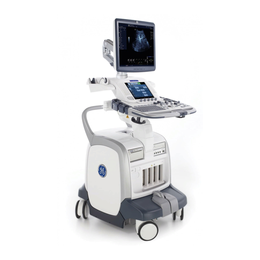
Manuals and User Guides for GE LOGIQ E9. We have
6
GE LOGIQ E9 manuals available for free PDF download: Service Manual, User Manual, Technical Publication
GE LOGIQ E9 Service Manual (561 pages)
Brand:
GE
| Category:
Scanner
| Size: 20.2 MB
Table of Contents
Important Precautions
3
Certified Electrical Contractor Statement - for USA Only
12
Damage in Transportation
12
Omissions & Errors
12
Service Safety Considerations
12
List of Effected Pages (LOEP)
14
Revision History
14
Table of Contents
15
CHAPTER 1 Introduction
71
Overview
71
Purpose of this Chapter
71
Service Manual Overview
72
Indications for Use
72
Contents in this Service Manual
73
LOGIQ E9 Models Covered by this Manual
74
Typical Users of the “Basic” Service Manual
74
Product Description
75
Contents in this Sub-Section
75
Overview of the LOGIQ E9 Ultrasound Scanner
76
History - Hardware/Software Versions
76
History - Peripherals/Software Versions
76
Frus for Back End Processor
76
History - Supported Probes
76
How to Turn the Scanner on and off
76
How to Check for Hardware/Software Version and Installed Options
76
Purpose of the Operator Manual(S)
76
Important Conventions
77
Contents in this Section
77
Conventions Used in Book
77
Model Designations
77
Icons
77
Safety Precaution Messages
77
Standard Hazard Icons
78
Important Conventions
78
Standard Icons that Indicate that a Special Procedure Is to be Used
79
Product Icons
80
Direction 5180483-100, Rev
83
Product Labels on LOGIQ E9 Consoles Used in a Veterinary Environment
87
Safety Considerations
88
Contents in this Section
88
Introduction
88
Human Safety
88
Human Safety
89
Mechanical Safety
90
Electrical Safety
92
Safe Practices
92
Probes
92
Label Locations
92
Dangerous Procedure Warnings
93
Lockout/Tagout (LOTO) Requirements
94
Returning/Shipping Probes and Repair Parts
95
Electromagnetic Compatibility (EMC)
96
Compliance
96
Electrostatic Discharge (ESD) Prevention
96
What Is EMC?
96
Customer Assistance
97
Contact Information
97
System Manufacturer
99
Authorized Representative
99
5180483-100, Rev
100
CHAPTER 2 Site Preparations
101
Overview
101
Purpose of this Chapter
101
Contents in this Chapter
101
General Console Requirements
102
Contents in this Section
102
Console Environmental Requirements
102
Environmental Specifications
102
Cooling
102
Lighting
102
General Requirements
103
Electrical Specifications for the LOGIQ E9
103
Inrush Current
103
Electrical Requirements for LOGIQ E9
103
Site Circuit Breaker
104
Site Power Outlets
104
Power Stability Requirements
104
EMI Limitations
105
EMI Prevention/Abatement
105
Probes Environmental Requirements
106
Time and Manpower Requirements
106
Facility Needs
107
Purchaser Responsibilities
107
Contents in this Section
107
Required Facility Needs
108
Desirable Features
109
Minimal Floor Plan Suggestions
109
Networking Setup Requirements
111
Stand Alone Scanner (Without Network Connection)
111
Scanner Connected to Hospital's Network
111
Insite Requirements
111
Purpose of the DICOM Network Function
111
DICOM Option Setup Requirements
111
LOGIQ E9 Setup
113
CHAPTER 3 System Setup
113
Overview
113
Purpose of this Chapter
113
Contents in this Chapter
113
Average Setup Time
114
Setup Warnings
114
Setup Reminders
114
Receiving and Unpacking the Equipment
116
Purpose of this Section
116
Contents in this Section
116
Receiving the LOGIQ E9
117
Overview
117
Examine Package
117
Damage in Transportation
117
The Tilt and Shock Indicators
118
TIPNTELL Indicator and Label
118
Overview
118
LOGIQ E9 Transportation Box Label
119
Unpacking the LOGIQ E9
120
Uncrating Instructions
120
Packing Materials - Recycling Information
124
Preparing for Setup
124
Verify Customer Order
124
Physical Inspection
125
Back Cover Label and ETL Testing Laboratories Safety Rating Label (ETL May Not be Present)
126
Rating Plate Label - R3.X and Earlier 100-120V Shown
126
Rating Plate Label - R4.X.X
127
Rating Plate Label - R5.X.X
127
Rating Plate Label - R6.X.X
127
EMI Protection
129
Completing the Setup
130
Physical Dimensions
130
Physical Dimensions of LOGIQ E9 with Monitor and Peripherals
130
Weight with Monitor and Peripherals
130
Purpose of this Section
130
Contents in this Section
130
Acoustic Noise Output
130
Electrical Specifications for LOGIQ E9
131
Connections on the I/O Rear Panel
132
Connect Ethernet
132
Connect USB Flash Drive
133
Connections on the Patient I/O Panel
134
Connecting Probes
134
Connect ECG
134
Introduction to Connecting Probes
134
Connect a Probe
135
Disconnect a Probe
135
Power On/Boot up
136
Detailed Procedure
136
Warnings
136
Connect AC (Mains) Power to the LOGIQ E9
137
The Circuit Breaker and ON/OFF Button
137
Switch on the AC Power to LOGIQ E9
138
Screen on the Display
139
Power Shut down
140
System - Exit Menu - R1.X.X
140
System - Exit Menu
141
Complete Power down
142
Press Once on the ON/OFF Button
142
Exit Menu (R2.X.X and R3.X.X)
143
System - Exit Menu (R1 X.X)
143
System - Exit/Download Menu (R5 and Later)
144
Sleep Mode
145
Purpose of this Section
146
LOGIQ E9 Configuration
146
System Configuration
146
Contents in this Section
146
Approved Internal Peripherals (Optional)
147
Approved External Peripherals (Optional)
147
Optional Peripherals/Peripheral Connection
147
Contents in this Sub-Section
147
Additional Information
147
Printer/Dvr Checks
148
Peripheral Checks
148
Available Probes
148
Software Options Configuration
148
Test the DVR Microphone
148
Turn off Power to LOGIQ E9
148
Installing a Software Option
149
System Admin Screen, R1.X.X - Add Button
149
System Admin Screen, R2.X.X or Later - Add Button
149
Option Keys File in R5 and Later - Import
150
Connectivity Overview
151
Physical Connection
151
Stand-Alone LOGIQ E9
151
Sneaker Net Environment
151
Wired Ethernet from LOGIQ E9 to a Workstation
151
Connection Using Wireless Option (R2.X.X or Later)
151
Connectivity Setup and Tips
152
Setup the LOGIQ E9 for DICOM Communications
152
Utility -> Connectivity -> TCP/IP Screen
152
Utility -> Connectivity -> Device Screen
153
Devices, Services, Dataflows and Print Buttons
154
Dataflows
154
How to Get the LOGIQ E9 to Recognize Another Device on the Network
155
DICOM Image Storage Service
155
Initial Steps
156
Initial Steps - Setup an Image Storage Service
156
Properties
158
Sending Images and Data to a DICOM Image Storage Service
162
Dataflow
162
Print Button Setup - R3.X and Earlier
164
Print Button Settings
165
Print Button Setup - R4.X and Later
167
Send to
171
DICOM Print Service
172
Print Service Setup
172
Print Service Use
174
DICOM Worklist Service
175
Worklist Setup
175
New Field in Worklist Setup
176
R5.1.1 and Earlier
176
R5.1.2 and Later
176
"Remote” Versus “Local” Filtering
177
Dicom Value Representations
179
Worklist Use
180
DICOM MPPS (Modality Performed Procedure Step) Service
181
Setup and Use a DICOM MPPS
181
DICOM Storage Commitment Service
183
DICOM Storage Commitment Service Setup and Use
183
Structured Reporting
185
Sending Structure Report - R3.X and Earlier
186
Sending Structure Report - R4.X and Later
186
DICOM Query/Retrieve (Q/R) Service
187
Q/R Service Setup
187
Q/R Service Use
188
Q/R Support for Volume Navigation
189
Image History Display
189
LOGIQ E9 Scan Screen
190
Spooler
191
Dicom Job Spooler Display
191
Wireless
192
Network “Sniffer”
193
Encoded Value in the “Status” Tag
195
Wireshark: Save File as
196
Setup Paperwork
197
Contents in this Section
197
User Manual(S)
197
Product Locator Card.гвш
197
Configuring Insite Exc
198
Configuration Steps
198
Direction 5180483-100, Rev . 7 Logiq E9 Proprietary Service Manual
198
Contents in this Section
198
Prerequisites for Insite Exc Setup
198
Configuring Agent Configuration
199
Service Login Screen - LOGIQ E9
199
Configuring Insite Exc
199
Completed Agent Configuration Tool Screen - LOGIQ E9
201
Configuring Advanced Configuration
202
Submit Changes Response
202
Configuration Home Page - LOGIQ E9
203
Configuring Request for Service (RFS)
204
Remote Check and Configuration
204
Request for Service Setting on System Admin Page
204
Select Default Machine Contact
204
Service Safety Considerations
205
Gathering Troubleshooting Data
206
Collecting Vital System Information
207
ALT+D Dialog Box
208
Collecting a Screen Capture with Logs
208
Collecting a Screen Capture with Logs
209
Marking Log Files
209
Capture Service Example
210
Capturing Service Logs with ALT+D
210
Capturing Network Logs with Network Sniffer (Software R1.X.X)
211
Configuration Screen
211
Distinct Network Monitor Window
211
Configuration - Filters Tab
212
Enter Filter Settings
213
Capture Tab on Configuration Screen
214
Capture Data Sample
216
Save as Capture File Dialog Box
216
Capturing Network Logs with Network Sniffer (Software R2.X.X or Later)
217
Network Sniffer Screen
217
Sniffer Captions Options
217
Capture Filter IP Only
218
Sniffer Capture Filter IP and Port
219
Sniffer Window and Network Activity
220
Filter Tool Display
221
Select Capture Stop Icon
221
Save Capture Data Question
222
Select Capture Display
222
Ctrl+Printscreen Shortcut
223
Screen Captures
223
To Capture a Screen Image Using the Shortcut
223
Common Service Desktop
224
Common Service Desktop Overview
226
Global Service User Interface (GSUI)
227
Internationalization
227
Service Login
227
Service Login Screen- LOGIQ E9
227
Access Authorization
228
Restart LOGIQ E9 after Diagnostics
228
Home
229
Home Window
229
Server History Log
230
Error Logs
231
Error Logs - Log Viewer
231
Log Viewer - Log Options
231
Log Viewer - Sample Page
232
Diagnostics Window Overview
233
Details Link on Diagnostic Window
235
Details Table
236
Details Window
236
Diagnostic Symptom Guide
237
Diagnostic Utility Freezes Up/Times out
237
GFI FRU Tests Table
239
Digital Receive Tests Table
240
Memory Tests Table
240
Analog Receive Tests Table
241
Noise Test Table
241
System Tests Table
241
Analog CW Tests Table
242
Transmit Tests Table
242
I/O Board Tests Table
243
Transmit and Receive Tests Table
243
Tx Power Supply Tests Table
243
Baybird Tests Table
244
Extended Power Shutdown Tests Table
244
BEP Interactive Tests Table
245
BEP Tests Table
245
4D Motor Controller Tests Table
246
DVR Tests Table
246
Patient I/O Test Table
246
Touch Panel Tests Table
246
Accessing the Service Platform from Windows
248
OP Panel Utilities - Op Panel Interface
248
Launching the Op Panel Test
249
Trackball Tab
253
Trackball Tab - R4 and Earlier
253
Trackball Tab - R5 and Later
253
Keyboard Tab
254
Keyboard Tab - R4 and Earlier
254
Keyboard Tab - R5 and Later
254
Slidepots Tab
255
Slidepots Tab - R4 and Earlier
255
Slidepots Tab - R5 and Later
255
Encoders Tab
256
Encoders Tab - R4 and Earlier
256
Encoders Tab - R5 and Later
256
Pushbuttons Tab
257
Pushbuttons Tab - R4 and Earlier
257
Pushbuttons Tab - R5 and Later
257
Leds Tab
258
Leds Tab - R4 and Earlier
258
Leds Tab - R5 and Later
258
Touch Screen Tab
259
Touch Screen Tab - R4 and Earlier
259
Touch Screen Tab - R5 and Later
259
Diagnostics - Common Diagnostics
260
Disruptive Mode
260
Disruptive Mode Utility Window
260
System Shutdown
261
System Shutdown Window
261
Diagnostics for Service Diagnostics
262
Digital Receive Window
262
Memory
266
Memory Window
266
Gfi
269
GFI Window
269
System
272
System Window
272
Noise Window
274
Transmit
275
Transmit/Receive
276
Analog Receive
277
Analog Receive Window
277
Analog CW
279
Analog CW and Patient I/O Service Diagnostics Options
279
Analog Continuous Wave (CW) Doppler Tests
280
I/O Board Tests
286
I/O Board Tests Window
286
Tx Power Supply Test
290
Tx Power Supply Tests Window
290
EPS (Extended Power Shutdown) or CB (Chargeboard Used in BEP6) Tests
292
EPS or CB Tests Window
292
Baybird Tests
294
Baybird Tests Window
294
Diagnostics Menu - MRX
298
Diagnostics Menus on R3.X.X and Later
298
Diagnostics Window Overview - R3.X.X and Later
298
Determine Hardware Platform
299
System Main Board for MRX
300
System Main Board Tests for MRX
300
Front End Interface
301
Digital Receive
303
Digital Receive - Board Tested/Required Matrix for Diagnostics
303
Transmit - Board Tested/Required Matrix for Diagnostics
305
Memory - Board Tested/Required Matrix for Diagnostics
306
Memory - MRX
306
System - Board Tested/Required Matrix for Diagnostics
307
Analog Receive - Board Tested/Required Matrix for Diagnostics
308
Analog CW - Board Tested/Required Matrix for Diagnostics
310
Noise
311
Noise - Board Tested/Required Matrix for Diagnostics
311
Back End Tests
312
Back End Tests - MRX
312
Power Test Includes Tests on the Transmit Power Supply and the EPS
312
Transmit/Receive - Board Tested/Required Matrix for Diagnostics
312
Miscellaneous Tests
313
Miscellaneous Tests - MRX
313
DVR Test Screen
314
DVR Tests
314
BEP Test Description Table for R3.X and Earlier
315
BEP Test Description Table for R4.X and Later
315
Diagnostics - BEP
315
Essential Tests
316
Essential Tests Differences in R4 and Later
316
Essential Tests Window
316
System Board
318
System Board Window
318
Hard Disk Drive Surface Scan
319
Hard Disk Drive Surface Scan Window
319
Hard Disk Drive Quick Test
320
Hard Disk Drive Quick Test Window
320
Video Card
321
Video Card Window
321
S-Video Image Displays a Portion of the Main Display
322
The Monitor Measurement Summary Sidebar Does Not Appear after Upgrading to R6
322
Monitor Adjustment Controls Do Not Show for the OLED Monitor
323
Un-Install and Re-Install the Driver Manually
323
Network Adapter
324
Network Interface Window
324
Network Adapter Diagnostic Changes for R4
325
Network Adapter Diagnostics Window - R4
325
BEP Interactive Test Description Table - R3.X and Earlier
327
Diagnostics - BEP Interactive Tests
327
BEP Interactive Test Description Table - R4.X
328
Diagnostics - BEP Interactive Tests - R4.X and Later
328
Keyboard
329
Keyboard Window
329
Footswitch Tests
330
Mouse (Trackball)
331
Mouse Window
331
Audio (Sound)
332
Audio Window
332
Calibration
333
Touch Panel
333
Touch Panel Calibration Screen
333
Calibration Verification
334
Touch Panel Calibration Verification Screen
334
4D Motor Controller
335
4D Motor Controller Screen
335
Patient I/O Tests
337
Software Options Interface
338
Software Options Interface Window
338
Insite Exc Agent Configuration
339
Insite Exc Agent Configuration Window
339
Application Log Window Example
340
Event Log Viewer
340
Event Log Viewer Window
340
Utilities - Common Utilities
340
Disk Usage
341
Disk Usage Window
341
IP Configuration
342
IP Configuration Window
342
Network Status
342
Network Status Window
342
Windows Services
343
Windows Services Window
343
Shared Resources
344
Shared Resources Window
344
User Account Window
344
User Accounts
344
Gather Logs Utility
347
Gather Logs Utility Window
347
Image Viewer Utility
348
Image Viewer Utility Window
348
Image Compress & Delete Utility
349
Image Compress & Delete Utility Window
349
Scanner Documentation Interface
350
Distinct Network Monitor R1.X.X
351
Virtual Console Observation (VCO)
352
Telnet Server Control
353
Telnet Server Control Window
353
Invoke Software Reload
354
Invoke Software Reload - R2.X.X and R3.X
354
Invoke Software Reload - R4 and Later
354
Invoke Software Rollback
355
Clean-Up SW Package Repository
356
DICOM Verify
357
DICOM Verify Window
357
Utilities - Scanner Utilities
357
Replacement
358
Replacement Window
358
Pm
359
PM Window
359
Wireless Network Configuration (WLAN Diagnostics)
360
Wireless Networks Window
360
Wireless Properties Window
361
Wireless Monitor Window
362
Wireless Securities Window
363
Network Adapter Diagnostic Changes for R4 and Later
364
Wired LAN Network Adapter Test Window
364
Troubleshooting Using Insite Exc
368
CIS_CSD (Rsvp) Remote Tools Tab
369
How to Access CSD Remotely
369
Reconnect to the Device
369
How FE Remotely Enables Disruptive Mode and VCO
370
Service Log Screen
370
Insite Exc Notification
371
Disruptive Mode Enabled
372
Virtual Console Observation Is Running
372
Virtual Console Observation Is Stopped
373
Virtual Console Observation “Warning”
373
“Totalaccess” Window
374
How Customer Enables Disruptive Mode
375
Service Login Screen
375
Customer Enables VCO
377
Troubleshooting Insite Exc Configuration
378
Troubleshooting Flowchart
379
Troubleshooting Trees
380
5180483-100, Rev
381
LOGIQ E9 Does Not Power on / Boot up
381
Power on / Boot up Flowchart
381
Advertisement
GE LOGIQ E9 Service Manual (754 pages)
Brand:
GE
| Category:
Medical Equipment
| Size: 55.03 MB
Table of Contents
Important Precautions
3
Revision History
14
Chapter 1 Introduction
15
Section 1-1 Overview
15
Purpose of this Chapter
15
Section 1-2 Service Manual Overview
15
Product Description
18
Section 1-3 Important Conventions
19
Product Icons
22
Section 1-4 Safety Considerations
30
Mechanical Safety
32
Electrical Safety
34
Section 1-5 Label Locations
34
Dangerous Procedure Warnings
35
Lockout/Tagout (LOTO) Requirements
36
Electromagnetic Compatibility (Emc)
38
Section 1-10 Customer Assistance
39
Contact Information
39
System Manufacturer
41
Chapter 2 Site Preparations
43
Section 2-1 Overview
43
Purpose of this Chapter
43
General Console Requirements
44
Console Environmental Requirements
44
Environmental Specifications
44
Electrical Requirements
45
EMI Limitations
47
Time and Manpower Requirements
48
Desirable Features
51
Networking Setup Requirements
53
Section 3-2 Setup Reminders
56
Setup Warnings
56
Receiving and Unpacking the Equipment
58
Purpose of this Section
58
Packing Materials - Recycling Information
66
Section 3-5 Preparing for Setup
66
Verify Customer Order
66
EMI Protection
71
Section 3-6 Completing the Setup
72
Electrical Specifications
73
Connect Ethernet
74
Power On/Boot up
77
Power Shut down
81
System Configuration
85
Available Probes
87
Installation
90
Section 4-1 Overview
91
Purpose of this Chapter
91
Section 4-2 General Procedures
92
Complete Power down
97
Removable Media
102
Archiving and Loading Presets
102
Space Management
102
Performance Tests
117
B-Mode Checks
118
Basic Measurements
124
Report Pages
125
Backup and Restore Database, Preset Configurations and Images
126
Mechanical Function Checks
130
Software Configuration Checks
133
Power Supply Test Procedure
133
Section 4-8 Site Log
135
Chapter 5 Components and Functions (Theory)
141
Section 5-1 Overview
141
Purpose of this Chapter
141
Purpose of this Section
142
Color Flow Doppler Mode
147
Pulsed (PW) Doppler
148
Continuous Wave (CW) Doppler
148
Other Modes
148
Contrast Imaging
149
Operator Panel
158
Section 5-4 Main Console
160
Section 5-5 Air Flow Control
161
General Description
161
Section 5-7 Power Distribution
162
Power down
167
Section 5-11 Product Manuals
175
User Documentation
175
Service Documentation
175
Chapter 6 Service Adjustments
177
Purpose of this Chapter
177
Section 6-2 Monitor Adjustments
177
Purpose of this Section
177
Monitor Adjustment Procedure
180
Cautions and Warnings
189
Chapter 7 Diagnostics/Troubleshooting
203
Section 7-1 Overview
203
Applications Software
204
Section 7-4 Screen Captures
214
Purpose of this Section
214
Error Logs
216
Keyboard Tab
225
Ending the Program
230
Name: System
266
Touch Panel
275
Calibration Verification
275
Motor Controller
276
Disk Defragmenter
280
Chapter 8 Replacement Procedures
285
Section 8-1 Overview
285
Purpose of this Section
286
Returning/Shipping Probes and Repair Parts
288
Loading the Software
293
Symantec Ghost Window
296
Purpose of this Section
311
Top Cover Replacement
319
Front Cover Replacement
326
Front Cover Installation
327
Calibration and Adjustments
328
Rear Cover Installation
337
Calibration and Adjustments
344
Rear Bumper Replacement
345
Purpose of this Section
369
Calibration and Adjustments
420
Calibration and Adjustments
438
Purpose of this Section
469
Calibration and Adjustments
484
Purpose of this Section
485
Calibration and Adjustments
508
HDD Removal
511
Calibration and Adjustments
554
Option Contents
585
Routine Maintenance
592
Parts Required
594
GE LOGIQ E9 Service Manual (808 pages)
Brand:
GE
| Category:
Medical Equipment
| Size: 49.17 MB
Table of Contents
Table of Contents
3
CHAPTER 1 Introduction
25
Overview
25
Service Manual Overview
25
Important Conventions
29
Safety Considerations
39
Label Locations
44
Dangerous Procedure Warnings
45
Lockout/Tagout (LOTO) Requirements
46
Returning/Shipping Probes and Repair Parts
47
Electromagnetic Compatibility (EMC)
48
Customer Assistance
50
CHAPTER 3 LOGIQ E9 Setup
53
Overview
53
Setup Reminders
66
Receiving and Unpacking the Equipment
68
Packing Materials - Recycling Information
76
Preparing for Setup
77
Completing the Setup
80
Configuration
96
Connectivity Overview
101
Connectivity Setup and Tips
102
Setup Paperwork
144
CHAPTER 4 Functional Checks
145
Overview
145
General Procedures
146
Functional Checks
175
Application Turnover Check List
191
Power Supply Test and Adjustments
191
3D/4D and Volume Navigation Functional Check
192
SWAVE (Shear Wave "Shear Elasto") Functional Check
192
Site Log
193
CHAPTER 5 Components and Functions (Theory)
199
Overview
199
LOGIQ E9 Description
201
Top Console with LCD Monitor and Operator Panel
214
Main Console
219
Air Flow Control
220
Casters and Brakes Description
220
Power Distribution
221
Power Loss Description
231
Cables for LOGIQ E9
231
Probes Description
231
Product Manuals
232
CHAPTER 6 Service Adjustments
233
Overview
233
LCD Monitor Adjustments
236
DC Offset Calibration
240
Operator Panel Movement
241
Direction Lock and Brake Adjustments
248
Adjust Time-Out for DICOM Servers
248
CHAPTER 8 Replacement Procedures
347
Overview
347
Warnings and Important Information
348
Definitions of Left, Rear / Back, Right and Front
352
Loading / Reloading / Upgrading the Software
353
Replacing Covers and Bumpers
375
Replacing Top Console Parts
433
Main Console Parts Replacement
521
Casters and Brakes Replacement
538
BEP (Back End Processor) Parts Replacement
544
Main Power Supply Parts Replacement
590
Peripherals Replacement
615
Nav Roll Stand And/Or On-Board Stand Installation And/Or Replacement
644
CHAPTER 9 Renewal Parts
663
Overview
663
Definitions of Left, Rear / Back, Right and Front
663
List of Abbreviations
664
LOGIQ E9 Models and Hardware/Software Compatibility
666
Software
667
Covers and Bumpers
671
Top Console Parts
697
XYZ Mechanism Parts
701
Main Console Parts
706
Casters (Wheels) Parts
708
Card Rack Parts
712
Back End Processor (BEP) Parts
730
Main Power Supply Parts
736
Peripherals
738
Mains Power Cables
744
Internal Cables
746
Probes
764
Options
768
Product Labels on LOGIQ E9 Consoles Used in a Veterinary Environment
773
Hardware Kit
774
Advertisement
GE LOGIQ E9 Service Manual (722 pages)
Brand:
GE
| Category:
Medical Equipment
| Size: 38.93 MB
GE LOGIQ E9 User Manual (256 pages)
Brand:
GE
| Category:
Medical Equipment
| Size: 2.21 MB
Table of Contents
Revision History
3
Regulatory Requirements
5
Table of Contents
9
Chapter 1 - Getting Started
14
Console Overview
14
Attention
14
Prescription Device
14
Indications for Use
15
Contraindication
16
Important Notices
17
Console Graphics
19
Moving the System
30
Before Moving the System
30
When Moving the System
32
Operator Panel Movement Controls
33
Setting the Front Wheels Lock
35
System Start-Up
36
Power on
36
Power off
37
Circuit Breaker
39
Probes
40
Introduction
40
Connecting the Probe
41
Cable Handling
42
Activating the Probe
42
Disconnecting the Probe
43
Probe Discussion
43
Convex Probes
44
Linear Probes
46
Sector Probes
47
Biopsy Special Concerns
53
Preparing for a Biopsy
55
Surgery/Intra-Operative Use
76
Beginning an Exam
78
Scanning a New Patient
78
Patient Screen
80
Chapter 2 - Performing an Exam
88
Optimizing the Image
88
B-Mode Controls
88
Color Flow Mode Controls
91
M-Mode Controls
93
M Color Flow Mode
93
Doppler Mode Controls
94
3D Mode
96
Other Controls
97
Measurement and Analysis
102
Introduction
102
Location of Measurement Controls
103
B-Mode Measurements
104
Doppler Mode Measurements
112
M-Mode Measurements
115
Viewing and Editing Worksheets
117
Clinical Measurement Accuracy
122
Setting up the Off-Line Paper Printer
125
Chapter 3 - after the Exam Is over
128
Probe Overview
128
Probe Naming Conventions
128
Probe Handling and Infection Control
129
Endocavitary Probe Handling Precautions
130
Probe Cleaning Process
131
Coupling Gels
142
System Presets
144
Foreign Language Keyboard Setup
144
Data Backup
151
Ezbackup and Ezmove
151
Backup Procedure: User-Defined Configurations
158
Restore Procedure: Patient Data
159
Restore Procedure: User-Defined Configurations
160
Configuring Connectivity
161
Overview
161
Connectivity Functions
162
Anti-Virus Software Note
163
Electronic Documentation
165
Accessing Documentation Via a Windows PC
165
Accessing Documentation on the Ultrasound Scanner Via the Media
166
Using Online Help Via F1
167
Contact Information
168
Contacting GE Healthcare Ultrasound
168
Manufacturer
174
System Data
175
Features/Specifications
175
System Overview
176
System Care and Maintenance
181
Expected Service Life Description
181
Inspecting the System
182
Cleaning the System
184
Other Maintenance
189
Assistance
192
Supplies/Accessories
192
GE LOGIQ E9 Technical Publication (127 pages)
Ultrasound System
Brand:
GE
| Category:
Medical Equipment
| Size: 3.71 MB
Table of Contents
Table of Contents
21
Chapter 1 - Overview
25
Content in this Manual
26
Product Description
27
Overview of the Ultrasound System
27
Products Covered in this Manual
28
Chapter 2 - Safety Information
29
Overview
30
Contents in this Chapter
30
Important Conventions
31
Conventions Used in Book
31
Standard Hazard Icons
33
Product Icons
35
Label Icon Description
35
How to Lock the Operator Panel Prior to Transport
35
Safety Considerations
36
Introduction
36
Human Safety
36
Mechanical Safety
39
Electrical Safety
44
Label Locations
46
Product Labels
46
Dangerous Procedure Warnings
47
Warnings
47
Lockout/Tagout (LOTO)
48
LOTO Requirements
48
Returning Probes and Repair Parts
49
Requirements for Returning Parts
49
User Responsibility
49
Electromagnetic Compatibility (EMC)
50
What Is EMC
50
Compliance
50
Electrostatic Discharge (ESD) Prevention
51
Chapter 3 - Site Preparations
53
Overview
54
Contents in this Chapter
54
General Ultrasound System Requirements
55
Contents in this Section
55
Ultrasound System Environmental Requirements
55
Electrical Requirements
57
EMI Limitations
70
Probes Environmental Requirements
72
Time and Manpower Requirements
72
Facility Needs
73
Contents in this Section
73
Purchaser Responsibilities
73
Required Facility Needs
75
Desirable Features
77
Care and Maintenance
79
Contents in this Chapter
80
Chapter 4 - Care and Maintenance
81
Warnings
81
Why Do Maintenance
82
Keeping Records
82
Quality Assurance
82
Maintenance Task Schedule
83
How Often Should Maintenance Tasks be Performed
83
System Maintenance
84
Preliminary Checks
84
Functional Checks
85
Physical Inspection
87
Cleaning
89
Probe Maintenance
90
Using a Phantom
91
Phantoms
91
Electrical Safety Tests
92
Content in this Section
92
Uninterrupted Power Supply (UPS)
93
Safety Test Overview
94
Leakage Current Limits
97
Outlet Test - Wiring Arrangement - USA and Canada
101
Grounding Continuity
102
Chassis Leakage Current Test
103
Isolated Patient Lead (Source) Leakage-Lead to Ground
107
Isolated Patient Lead (Source) Leakage-Lead to Lead
109
Isolated Patient Lead (Sink) Leakage-Isolation Test
111
Probe (Source) Leakage Current Test
113
Isolated Probe (Sink) Leakage-Isolation Test
118
When There's too Much Leakage Current
122
AC/DC Fails
122
Chassis Fails
122
Probe Fails
123
Peripheral Fails
123
Still Fails
123
New Ultrasound System
123
ECG Fails
123
Ultrasound Equipment Quality Check (EQC and IQC)
124
Quality Checks
124
Advertisement
Related Products
GE Evolution Series E9000
GE Vivid E90
GE Vivid E95
GE EER2000
GE Triton EDW2020
GE ESL25XGSBBS and
GE EGD4600
GE EasyCam Pro
GE EZ4-1100
GE EHM
GE Categories
Refrigerator
Ranges
Microwave Oven
Air Conditioner
Dishwasher
More GE Manuals
Login
Sign In
OR
Sign in with Facebook
Sign in with Google
Upload manual
Upload from disk
Upload from URL