Sign In
Upload
Manuals
Brands
GE Manuals
Medical Equipment
LOGIQ 9
GE LOGIQ 9 Manuals
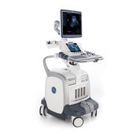
Manuals and User Guides for GE LOGIQ 9. We have
2
GE LOGIQ 9 manuals available for free PDF download: Technical Manual, Technical Publication
GE LOGIQ 9 Technical Manual (570 pages)
Brand:
GE
| Category:
Medical Equipment
| Size: 27.64 MB
Table of Contents
Table of Contents
9
Overview
39
Purpose of Service Manual
39
Typical Users of the Basic Service Manual
40
LOGIQ™ 9 Models Covered by this Manual
40
Purpose of Operator Manual(S)
40
Important Conventions
41
Conventions Used in Book
41
Standard Hazard Icons
42
Product Icons
43
Chapter 1 Introduction
43
Safety Considerations
45
Introduction
45
Human Safety
45
Mechanical Safety
45
Electrical Safety
46
Labels Locations
46
Dangerous Procedure Warnings
47
Lockout/Tagout Requirements (for USA Only)
47
Returning/Shipping Probes and Repair Parts
47
EMC, EMI, and ESD
48
Electromagnetic Compatibility (EMC)
48
CE Compliance
48
Electrostatic Discharge (ESD) Prevention
48
Customer Assistance
49
Contact Information
49
System Manufacturer
50
CHAPTER 2 Pre-Installation
51
Overview
51
Purpose of Chapter 2
51
General Console Requirements
52
Console Environmental Requirements
52
Cooling
52
Lighting
52
Electrical Requirements
52
Inrush Current
52
LOGIQ™ 9 Power Requirements
52
Power Stability Requirements
53
Site Circuit Breaker
53
Site Power Outlets
53
Unit Power Plug
53
EMI Limitations
54
Scan Probe Environmental Requirements
55
Time and Manpower Requirements
55
Facility Needs
56
Purchaser Responsibilities
56
Required Features
57
Desirable Features
57
Minimal Floor Plan Suggestion
58
Networking Pre-Installation Requirements
59
DICOM Option Pre-Installation Requirements
59
Purpose of the DICOM Network Function
59
CHAPTER 3 Installation
61
Overview
61
The Purpose of Chapter 3
61
Installation Reminders
62
Average Installation Time
62
Installation Warnings
62
Brake Pedal Operation
62
Operator I/O Panel Position
62
Safety Reminders
63
Receiving and Unpacking the Equipment
64
Preparing for Installation
65
Verify Customer Order
65
Physical Inspection
65
System Voltage Settings
65
Video Formats
65
EMI Protection
65
Completing the Installation
66
Power on / Boot up
66
Scanner Power on
66
Back-End Processor Boot up
67
Power Off/ Shutdown
67
Back-End Processor Power down
67
Scanner Shutdown
68
Transducer Connection
68
System Configuration
69
System Specifications
69
Acoustic Noise Output
69
Physical Dimensions Physical Dimensions of
69
Weight Without Monitor and Peripherals
69
Electrical Specifications
69
On-Board Optional Peripherals
69
External I/O Connector Panel
70
External I/O Pin Outs
72
Video Specification
74
Available Probes
75
Software/Option Configuration
75
Irection Evision Logiq™ 9 Proprietary Anual
75
Connectivity Installation Worksheet
76
Insite IP Address Configuration
77
Before Starting a Software Upgrade
77
Printers
77
Save Connectivity Settings
77
Loading Base Image Software
78
System Checks
83
Loading Application Software
84
Loading Applications Software
84
System Setup
88
To Complete the System Setup
88
VCR Setup
88
Printer Setup
88
Print Key Assignment and Checkout
88
Restore Patient, Report, and User-Defined Presets
89
Cycle System Power
89
Optional Software Procedures
90
Serialno.txt File Creation
90
Optional Check Devices
91
Optional Procedure for Changing (Re-Mapping) Drive Letters
93
Possible Behavior of the First Power up after Application Load
98
GE USB Control Panel Driver Loss
98
If the System Is NOT on a Network
101
Installing USB Line Printer - HP970/990
104
Optional USB Line Printer - HP970/990
104
Paperwork
105
Product Locator Installation
105
User Manual(S)
105
CHAPTER 4 Functional Checks
107
Required Equipment
107
General Procedure
108
Back-End Processor Boot up
109
Scanner Shutdown
110
System Features
111
Touch Panel
112
Monitor Display
113
System B/M-Mode Checks
114
System CFM and PWD Checks
115
Basic Measurements
116
Worksheets
117
Deactivating the Probe
118
Adjusting the CINE Loop Playback Speed
119
Using the MOD (Magneto-Optical Drive)
120
Backup and Restore Database, Preset Configurations and Images
121
Backup System Presets and Configurations
122
Restore System Presets and Configurations
123
Archiving Images
124
ECG Check out (this Option Is Currently Not Available on the LOGIQ™ 9
126
Peripheral Checks
127
Mechanical Function Checks
128
Brakes and Direction Locks Checks
129
Site Log
130
Overview
131
CHAPTER 5 Components and Functions (Theory)
132
General Information
132
Block Diagram
133
Dataflow Control Description
134
Front End Processor
135
Feps3
136
XDIF (Transducer Interface) Board
137
TD, TD4, TD5 (Time Delay) Boards (8)
139
Scan Control Board (SCB, SCB2)
141
SCB, SCB2 High Level Features
142
Equalization (EQ) Board
144
Basic Functions
145
Signal Processing
146
B/M Mode Processor (BMP) Board
147
Receive Signal Processing
148
October
150
EBM/EBM2 Interface with XDIF Relay Board
151
B–Mode Output Blocks
152
Back End Processor (BEP)
153
Enclosure
154
Additional Memory (RAM)(BT'03, October 2003) - BEP2.2
155
Location of the Back End Processor
156
Input Signals
157
USB to Serial Adapter Cable Setup (RS232 Serial Port)
158
BEP Power on Path
159
BEP Power off Path
160
Operator Console Control PWA
161
Console Main Cable
162
Main Cable Connectors with Pinouts
163
Patient I/O (Currently Not Supported by the LOGIQ™ 9)
166
Internal I/O
167
Location in the Unit
170
Inputs
171
Outputs
173
Top Console
175
CHAPTER 6 Service Adjustments
176
Monitor
176
Input Signals
177
Output Signals
179
Modem
180
Power Distribution
182
Overview
183
AC Controller Differences
185
Mechanical Descriptions
187
Wheels/Brakes
188
Air Flow Control
189
Global Service User Interface (GSUI)
190
Service Home Page
191
Error Logs Tab
193
Logs
194
Utilities
195
Filter
196
CHAPTER 7 Diagnostics
197
Diagnostics Execution
198
Image Quality
199
Configuration
200
CHAPTER 8 Replacement
201
Remote Software/Option Installation and Updates
202
Overview
203
Monitor
204
Monitor Tilt
206
Procedure
207
Z-Release Cable and Gas Spring Adjustment
208
Z-Release Cable Adjustment
209
Cable Adjustment
210
Procedure
211
Gas Spring Adjustment
212
Emergency Release Procedure
213
Brake Arm Adjustment
214
Brake Arm Adjustment Procedure
215
Brake Adjustment
216
Rear Wheel Brakes Adjustment
217
Rear Wheel Removal Procedure
218
Overview
219
Gathering Trouble Data
220
Collect a Trouble Image with Logs
221
Screen Captures
222
Setting the P4 Key to Screen Capture
223
Capturing a Screen
224
Reset the P4 Key to Customer's Functionality
225
Virtual Console Observation
226
Use of "Virtual Console Observation"
229
Diagnostics
231
Acquisition Diagnostics
232
Automatic Troubleshooting
233
Reliability Testing
237
Diagnostic Listings
238
Diagnostic Groups
240
Board-Level BMP Diagnostics
242
Board-Level EQ Diagnostics
243
Board Level EBM Diagnostics
244
Board-Level TD Diagnostics
245
System-Level Digital Diagnostics
246
System-Level Analog Diagnostics
247
Diagnostic Utilities
251
Calibration Utilities
252
Preferred Test Strategy for PCI 9054 Interface
253
The PCI Interface Test Details
254
Preferred Test Strategy for Memory
255
Strategy for Testing the Internal Memory Cells
256
Strategy for Testing Multiple-Part Ram's
257
I/O Devices
258
Testing the Front Panel Keys
259
Front Panel Light Tests
261
Common Diagnostics
262
PC Diagnostics (Non-Interactive Tests)
263
Hard Drive Tests
264
CD/DVD Drive Test
265
USB Test
266
PC Diagnostics (Interactive Tests)
267
Troubleshooting Trees
268
System Does Not Boot
269
Noise in Image
274
Unable to Scan
275
Trackball
276
Minimum Cable Configuration for System to Boot
277
System Does Not Power off / Shutdown
278
Monitor Troubleshooting
279
Unable to Record to VCR
282
Printer Troubleshooting
283
CD-RW Troubleshooting
285
MOD Troubleshooting
286
Network Troubleshooting
287
Troubleshooting Tips
289
Power Supply
290
Image Artifacts
292
Connectivity
293
System Pings and Verifies but Does NOT Send
294
Drive Failures (CD or MOD)
295
No Remote Control for Peripherals
296
Overview
299
Returning/Shipping Probes and Repair Parts
301
Plastic Covers and Bumpers
302
Side Covers (with Bumper) Replacement Procedure
303
Side Cover Installation Procedure
304
Upper Rear Cover Replacement Procedure
305
Top Cover Replacement Procedure
306
Front Cover Replacement Procedure
307
Lower Rear Cover Replacement Procedure
308
Front Bumper Replacement Procedure
309
Rear Handle Replacement Procedure
310
Back End Processor Replacement Procedure
311
Back-End Processor Removal Procedure
312
Back-End Processor Installation Procedure
313
Back-End Processor Installation Procedure
314
Back End Processor Power Supply Replacement
317
Installing the New BEP Power Supply
322
Preparations (Click here to View the Cover Removal Video)
324
BEP 2.X HDD Replacement (2348186-31)
327
Loading Software
331
BEP CD-RW Drive Replacement Procedure (BEP 2.X and above Only)
332
CD-RW Drive Replacement Procedure
335
CD-RW Drive Replacement Procedure
336
BEP MOD Replacement Procedure (BEP 2.X and above Only)
337
MOD Drive Installation Procedure
342
Preparations (Click here to View the Cover Removal Video)
344
Patient I/O Replacement Procedure
346
Power Supply Battery Pack Replacement Procedure
348
Power Supply Battery Pack Installation Procedure
349
Before Starting a Software Upgrade
350
Image Management Guide
351
Export/Import (Moving Data between Ultrasound Systems)
352
Importing Data
353
Patient, Report, and User-Defined Backup Protocols
354
Loading Base Image Software
357
System Checks
362
Loading Application Software
363
Upgrading Application Software
367
System Setup
371
Restore Patient, Report, and User-Defined Presets
372
Optional Software Procedures
373
Optional Check Devices
374
Optional Procedure for Changing (Re-Mapping) Drive Letters
376
Possible Behavior of the First Power up after Application Load
381
If the System Is NOT on a Network
384
AC Transformer Replacement Procedure
387
AC Transformer Removal Procedure
388
Monitor Assembly Replacement Procedure
390
Preparations (Click here to View the Cover Removal Video)
391
Monitor Removal
392
Loudspeaker Assembly Replacement
393
Loudspeaker Removal Procedure
394
Loudspeaker Installation Procedure
395
Monitor Shelf Replacement Procedure
396
Mounting Procedure
397
Z-Release Handle Replacement
398
X/Y Release Handle Replacement
399
Console Lock Assembly Replacement Procedure
400
Console Lock Assembly Removal Procedure
401
Release Lock Assembly Replacement Procedure
402
Release Lock Removal Procedure
403
AC Controller Replacement Procedure
404
AC Controller Installation Procedure
405
Upper Operator Panel Replacement Procedure
406
Upper Operator Panel Installation Procedure
408
Lower Operator Panel Replacement Procedure
409
Operator Panel Removal Procedure
410
Keypad Replacement Procedure
411
Alpha-Numeric (A/N) Keyboard Replacement Procedure
412
A/N Keyboard Installation
416
Trackball Assembly Replacement Procedure
418
Trackball Removal Procedure
419
Fan Assembly Replacement Procedure
420
Fan Assembly Installation Procedure
422
External I/O Replacement Procedure
424
External I/O Installation Procedure
425
Internal I/O Replacement Procedure
426
Installation Procedure
427
Front End Processor Boards Replacement Procedure
428
Front End Board Removal Procedure
429
Front End Board Installation Procedure
430
Verify and Update Vital Product Data
433
How to Update Vital Product Data on LOGIQ™ 9
435
Acquisition Diagnostics - Read EEPROM Data
436
Modify VPD Text Files
437
Acquisition Diagnostics - Write New VPD Data to EEPROM
444
Rear Caster Replacement Procedure
445
Rear Caster Removal Procedure
446
Rear Caster Installation Procedure
448
Front Caster Replacement Procedure
449
Front Caster Removal Procedure
452
Front Caster Installation Procedure
453
Brake/Direction Lock Assembly Replacement Procedure
454
Brake Pedal and Direction Lock Removal Procedure
455
Brake Pedal Replacement Procedure
456
Frogleg Replacement Procedure
457
Frogleg Removal Procedure
458
Frogleg Installation Procedure
459
Left and Right Frogleg Bumper Replacement Procedure
460
Rear Crash Bumper Replacement Procedure
461
Inner Boss Bumper Removal Procedure
462
Inner Boss Crash Bumper Replacement Procedure
463
Upper and Lower Column Cover Replacement Procedure
464
Color Video Printer Replacement Procedure
465
Mounting Procedure
466
Differences in Replacing the Digital Color Printers
467
UP-D21 Installation Procedure
469
Black and White Video Printer Replacement Procedure
470
Black and White Video Printer Installation Procedure
471
VCR Replacement Procedure
472
Wireless Voice Scan Option
473
Microphone/Transmitter Assembly
475
Assemble Microphone
476
Receiver Setup
480
Transmitter Setup
484
Transmitter Adjustment
485
Volume Setup
487
Audio Setup Wizard
489
Overview
493
LOGIQ™ 9 Models Numbers
494
CHAPTER 9 Renewal Parts
495
Parts List Groups
495
External Covers
496
Additional Console Hardware
498
Operator I/O Mechanical Parts
500
Mechanical Kits
501
Bumper Kit, Frogleg
502
Operator Control Panel Brackets
503
Operator Control Panel Assembly
504
Monitor Assembly
506
Front End Processor Assembly
507
I/O Interfaces
510
Back End Processor Assembly
511
Interconnect Cables
517
Power Distribution
528
Air Distribution
529
Peripherals
530
Voice Scan
531
Customer Documentation
532
Probes
533
Overview
535
CHAPTER 10 Periodic Maintenance
536
Why Do Periodic Maintenance
536
Tools Required
538
Special Tools, Supplies and Equipment
540
System Periodic Maintenance
541
Functional Checks (See also Chapter 4)
542
Peripheral/Option Checks
543
Air Filter Cleaning
544
Optional Diagnostic Checks
545
Using a Phantom
546
GEMS Leakage Current Limits
547
Outlet Test - Wiring Arrangement - USA & Canada
548
Grounding Continuity
549
Dale 600 - Ground Continuity
550
Chassis Leakage Current Test
551
Dale 600 Meter Procedure
552
Data Sheet for Chassis Source Leakage Current
553
Generic Procedure
554
Isolated Patient Lead (Source) Leakage–Lead to Lead
556
Data Sheet for ECG Leakage Current
557
Probe Leakage Current Test
558
No Meter Probe Adapter Procedure
560
Data Sheet for Transducer Source Leakage Current
561
When There's too Much Leakage Current
562
Advertisement
GE LOGIQ 9 Technical Publication (127 pages)
Ultrasound System
Brand:
GE
| Category:
Medical Equipment
| Size: 3.71 MB
Table of Contents
Table of Contents
21
Chapter 1 - Overview
25
Content in this Manual
26
Product Description
27
Overview of the Ultrasound System
27
Products Covered in this Manual
28
Chapter 2 - Safety Information
29
Overview
30
Contents in this Chapter
30
Important Conventions
31
Conventions Used in Book
31
Standard Hazard Icons
33
Product Icons
35
Label Icon Description
35
How to Lock the Operator Panel Prior to Transport
35
Safety Considerations
36
Introduction
36
Human Safety
36
Mechanical Safety
39
Electrical Safety
44
Label Locations
46
Product Labels
46
Dangerous Procedure Warnings
47
Warnings
47
Lockout/Tagout (LOTO)
48
LOTO Requirements
48
Returning Probes and Repair Parts
49
Requirements for Returning Parts
49
User Responsibility
49
Electromagnetic Compatibility (EMC)
50
What Is EMC
50
Compliance
50
Electrostatic Discharge (ESD) Prevention
51
Chapter 3 - Site Preparations
53
Overview
54
Contents in this Chapter
54
General Ultrasound System Requirements
55
Contents in this Section
55
Ultrasound System Environmental Requirements
55
Electrical Requirements
57
EMI Limitations
70
Probes Environmental Requirements
72
Time and Manpower Requirements
72
Facility Needs
73
Contents in this Section
73
Purchaser Responsibilities
73
Required Facility Needs
75
Desirable Features
77
Care and Maintenance
79
Contents in this Chapter
80
Chapter 4 - Care and Maintenance
81
Warnings
81
Why Do Maintenance
82
Keeping Records
82
Quality Assurance
82
Maintenance Task Schedule
83
How Often Should Maintenance Tasks be Performed
83
System Maintenance
84
Preliminary Checks
84
Functional Checks
85
Physical Inspection
87
Cleaning
89
Probe Maintenance
90
Using a Phantom
91
Phantoms
91
Electrical Safety Tests
92
Content in this Section
92
Uninterrupted Power Supply (UPS)
93
Safety Test Overview
94
Leakage Current Limits
97
Outlet Test - Wiring Arrangement - USA and Canada
101
Grounding Continuity
102
Chassis Leakage Current Test
103
Isolated Patient Lead (Source) Leakage-Lead to Ground
107
Isolated Patient Lead (Source) Leakage-Lead to Lead
109
Isolated Patient Lead (Sink) Leakage-Isolation Test
111
Probe (Source) Leakage Current Test
113
Isolated Probe (Sink) Leakage-Isolation Test
118
When There's too Much Leakage Current
122
AC/DC Fails
122
Chassis Fails
122
Probe Fails
123
Peripheral Fails
123
Still Fails
123
New Ultrasound System
123
ECG Fails
123
Ultrasound Equipment Quality Check (EQC and IQC)
124
Quality Checks
124
Advertisement
Related Products
GE LOGIQ 5 PRO
GE LOGIQ V3
GE LOGIQ 400
GE LOGIQ P3 EXPERT
GE LOGIQ e
GE LOGIQ F Series
GE LOGIQ S6
GE LOGIQ 5
GE LOGIQ 3
GE LOGIQworks Workstation
GE Categories
Refrigerator
Ranges
Microwave Oven
Air Conditioner
Dishwasher
More GE Manuals
Login
Sign In
OR
Sign in with Facebook
Sign in with Google
Upload manual
Upload from disk
Upload from URL