Sign In
Upload
Manuals
Brands
Epson Manuals
Robotics
RC520
Epson RC520 Manuals
Manuals and User Guides for Epson RC520. We have
2
Epson RC520 manuals available for free PDF download: Manual, Safety And Installation
Epson RC520 Manual (208 pages)
ROBOT CONTROLLER
Brand:
Epson
| Category:
Controller
| Size: 11.02 MB
Table of Contents
Before Reading this Manual
7
Table of Contents
9
Setup & Operation
15
Safety
17
Conventions
17
Safety Precautions
17
Safety Features
20
Part Names and Functions
23
Model Number
23
System Configuration
23
Standard Specifications
25
Control Unit
27
Front Panel
27
Rear Panel
30
Dimensions
32
Control Unit Capability
32
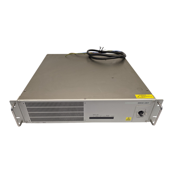
Four-Axis Drive Unit (RC520DU)
33
Four-Axis Drive Unit
33
Front Panel
33
Locking out the Four-Axis Drive Unit
34
Rear Panel
34
Four-Axis Drive Unit - Interior Layout
35
Dimensions
37
Six-Axis Drive Unit (RC520DU6)
38
Six-Axis Drive Unit
38
Front Panel
38
Locking out the Six-Axis Drive Unit
39
Rear Panel
39
Six-Axis Drive Unit - Interior Layout
40
Dimensions
42
Installation
43
Environmental Requirements
43
Power Supply
44
Specifications
44
Power Plug
45
Cable Connection
46
Typical Cable Connections (Single Manipulator)
47
Connecting Drive Unit and Control Unit
50
Connecting a Drive Unit to the Manipulator
52
Noise Countermeasures
54
OPTIONAL DEVICE Connector
57
ATTEND (TEACH) Control Device
58
OPTIOINAL DEVICE Dummy Plug
59
Pin Assignments
60
EMERGENCY Connector
61
Safety Door Switch and Latch Release Switch
61
Safety Door Switch
61
Latch Release Switch
62
Checking Latch Release Switch Operation
62
Emergency Stop Switch
63
Checking Emergency Stop Switch Operation
63
STOP Box
64
Checking E. STOP Box Operation
64
Pin Assignments
65
Circuit Diagrams
66
Typical Application
66
Example 2: External Safety Relay Typical
67
Application
67
Multi-Manipulator
68
D-I/O Connector
69
Input Circuit
70
Output Circuit
72
Pin Assignments
74
D-I/O Connector - Pin Assignments
74
D-I/O Connector Optional Cable - Pin Assignments
75
D-I/O Connector Optional Cable for USA Specification - Pin Assignments
76
Expansion I/O Board - Optional
77
Expansion I/O Board
77
Protected Expansion I/O Board
78
Jumper Settings
78
Input Circuit
79
Output Circuit
81
Expansion I/O Board
83
Jumper Settings
83
Input Circuit
83
Output Circuit
84
Expansion I/O Board: Pin Assignments
86
Pin Assignments (NPN Type)
86
Pin Assignments (PNP Type)
88
Expansion I/O Connector
90
Pin Layout of Expansion I/O Connector
90
Expansion I/O Connector Cable
90
Expansion I/O Connector Cable - Pin Assignments
91
I/O Remote Settings
95
Remote I/O Signal Descriptions (EPSON RC+)
95
Remote Input Signals
96
Remote Output Signals
98
Remote I/O Signal Descriptions (SPEL CT)
99
Remote Input Signals
99
Remote Output Signals
101
Timing Specifications (EPSON RC+)
103
Design Notes for Remote Input Signals
103
Timing Diagram for Operation Execution Sequence
103
Timing Diagram for Program Execution Sequence
104
Timing Diagram for Safety Door Input Sequence
105
Timing Diagram for Emergency Stop Sequence
105
Timing Diagram for RECOVER Sequence
106
Timing Specifications (SPEL CT)
108
Design Notes for Remote Input Signal
108
Timing Diagram for Operation Execution Sequence
108
Timing Diagram for Program Execution Sequence
109
Timing Diagram for Safety Door Input Sequence
110
Timing Diagram for Emergency Stop Sequence
111
Timing Diagram for Error Generating Sequence
111
Timing Diagram for RECOVER Sequence
112
RS-232C Settings
115
RS-232C Cable
115
Pin Assignments
115
Connection Example
116
Preparation for Communication
116
Jumper Settings for MIB
117
Stand-Alone Option for RC520
121
Stand-Alone Option
121
System Configuration
121
Installation
121
Power Supply
122
Emergency Connector Plate Kit
122
Appearance of Emergency Connector Plate Kit
122
Components of Emergency Connector Plate Kit
123
Safety Door Switch and Emergency Stop Switch
123
Pin Assignments
124
Circuit Diagram
125
Mib
127
Board Number
127
Jumper Settings
127
Safety Precautions for Maintenance
131
Procedure for Lockout
133
Tagout
133
Regular Maintenance Inspection
135
Schedule for Maintenance Inspection
135
Inspection Point
136
Inspection While the Controller Is Turned off
136
Inspection While the Controller Is Turned on
136
Cleaning the Fan Filter
136
Replacing a Lithium Battery on the CPU Board
136
Backup of Data
138
Epson Rc
138
Spel Ct
143
Hardware Configuration
147
Control Unit, Drive Unit and Manipulator
147
Optional Boards
148
Control Unit
149
Overview
149
Replacing the MIB
149
Replacing CPU Board
150
Replacing an Optional Board
152
Replacing the System Panel
152
Removal of the System Panel
152
Installation of the System Panel
153
Cleaning and Replacing the Fan Filter
154
Replacing the Fan
155
Replacing the HDD (Hard Disk Drive)
156
Replacing the Emergency Connector Plate Kit
156
Four-Axis Drive Unit (RC520DU)
157
Overview
157
Pin Assignments for the System Connectors
158
M/C Power
158
M/C Signal
159
Motion
160
Four-Axis Drive Unit
161
System Configuration of Four-Axis Drive Unit
161
Module Functions and Layout
162
Inspecting the Switching Power Supply Module
163
Motor Driver Module
164
Layout and Functions
164
Replacing a Motor Driver Module
165
DPB (Drive Power Board)
167
Layout and Functions
167
Adjusting Encoder Voltage
169
Adjusting +5V Voltage
170
DMB (Drive Main Board)
171
Layout and Functions
171
Replacing the DMB
172
Cooling Fan
175
Layout
175
Inspecting the Fan Filter
175
Replacing the Fan
176
Regeneration Module (for RC520DU)
178
Layout and Function
178
Replacing a Regeneration Module (for RC520DU)
178
Six-Axis Drive Unit (RC520DU6)
181
Overview
181
Pin Assignments for the System Connectors
182
M/C Power
182
M/C Signal
183
Motion
183
Six-Axis Drive Unit
184
System Configuration of Six-Axis Drive Unit
184
Module Functions and Layout
185
Inspecting the Switching Power Supply Module
186
DPB (Drive Power Board)
187
Layout and Functions
187
DMB (Drive Main Board)
189
Layout and Functions
189
Replacing the DMB
189
Cooling Fan
192
Layout
192
Inspecting the Fan Filter
192
Replacing the Fan
193
Regeneration Module and Over-Voltage Detection Module (for RC520DU6)
195
Regeneration Module
195
Over-Voltage Detection Module
196
Verifying Manipulator Operation
197
Recovering the HDD
199
Recovering Windows
199
Configuring Windows
202
Setting up EPSON RC+ (for EPSON RC+ User)
203
Installing EPSON RC
203
Reserving Address Resources of EPSON RC+ Options
204
Setting up SPEL CT (for SPEL CT User)
205
Installing SPEL CT
205
Reserving Address Resources of SPEL CT Options
206
Maintenance Parts List
207
Advertisement
Epson RC520 Safety And Installation (64 pages)
Brand:
Epson
| Category:
Robotics
| Size: 1.39 MB
Table of Contents
Table of Contents
8
1 Safety
9
Conventions
9
Design and Installation Safety
10
Operation Safety
11
Maintenance Safety
14
Emergency Stop
17
Manipulator Labels
18
Safety Features
19
2 Installation
23
Example
24
Outline from Unpacking to Operation of Robot System
25
Unpacking
26
Transportation
27
Manipulator Installation
31
Controller Installation
35
Connecting Manipulator and Controller
39
Connecting Manipulator and Controller
49
Power-On
53
3 First Step
55
Windows XP Setup
55
Installing EPSON RC+ Software
56
Writing Your First Program
57
4 Second Step
61
Connection with External Equipment
61
Connection and Display Language4 of Op Tion OP500RC
62
5 Third Step
63
Advertisement
Related Products
Epson RC+
Epson RC90
Epson RC620 Series
Epson RC90-B
Epson RT3B-401SS
Epson RT6B-602SS
Epson RS Series
Epson RS3-351 Series
Epson RS4-551 Series
Epson RC700DU-A
Epson Categories
Printer
Projector
All in One Printer
Scanner
Printer Accessories
More Epson Manuals
Login
Sign In
OR
Sign in with Facebook
Sign in with Google
Upload manual
Upload from disk
Upload from URL