Sign In
Upload
Manuals
Brands
Canon Manuals
Copier
GP605
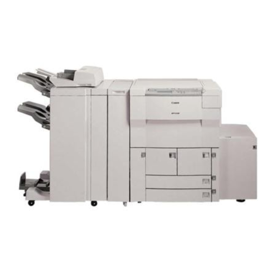
Canon GP605 Multifunction Laser Printer Manuals
Manuals and User Guides for Canon GP605 Multifunction Laser Printer. We have
1
Canon GP605 Multifunction Laser Printer manual available for free PDF download: Service Manual
Canon GP605 Service Manual (876 pages)
Brand:
Canon
| Category:
Copier
| Size: 15.75 MB
Table of Contents
Table of Contents
9
C. Extension Mode
23
Chapter 1 General Description
25
Features
25
Specifications
26
Copier
26
System
26
Type
26
Performance
27
Others
31
Side Paper Deck-C1
34
Names of Parts
35
External View
35
Cross Section
38
Operating the Copier
40
Turning on the Power Switch
40
Control Panel
41
Extension Mode
42
User Mode
43
Routine Maintenance by the User
45
Safety
46
Safety of Laser Light
46
CDRH Regulations
47
Handling the Laser Assembly
48
Safety of Toner
52
Image Formation
53
Outline
53
Chapter 2 Basic Operations
55
E. Inputs to and Outputs from the Major Pcbs
55
Basic Operations
57
Functional Construction
57
Electrical Circuitry
58
Image Processor PCB
58
Mfc Pcb
58
Outline
58
Control Panel CPU PCB
59
DC Controller PCB
59
Original Orientation Detection
59
Pcb
60
Basic Sequence of Operations
61
Controlling the Main Motor (M1)
62
Inputs to and Outputs from the Major Pcbs
63
Wiring Diagram of Major Pcbs
63
Inputs to the DC Controller PCB
64
Chapter 3 Original Exposure System
77
Operations
79
Outline
79
Basic Sequence of Operations
81
Changing the Reproduction Ratio
82
Pcb
84
Controlling the Scanner Motor
84
Outline
86
Controlling Pre-Heat Voltage
88
Controlling the Temperature by a Fluorescent Lamp Heater
88
Initial Activation
89
Detecting an Error
90
Detecting the Original Size
92
Detection by Original Sensors
92
Detection by the Feeder
92
Outline
92
Disassembly/Assembly
93
No. 1 Mirror Mount
94
Removing the Scanning Lamp/Scanning Lamp Heater
94
After Replacing the Scanning
97
Lamp
97
Points to Note When Replacing the Scanning Lamp
97
Removing the Scanner Motor
98
Scanner Drive Assembly
98
Scanner Drive Cable
99
C. Pcbs
106
Control Pcb
106
Removing the Light Intensity
106
Removing the Inverter Pcb
107
Position Sensor
111
Removing the Scanner Home
111
Chapter 4 Image Processing System
115
Outline
117
Analog Image Processing
120
Outline
120
Digital Image Processing
122
Outline
122
Block
123
Shading Correction
125
Line Conversion
126
Editing
127
Density Processing
128
Outline
128
Density Adjustment During Printing
130
Binary Processing
131
Dither Screen Method
131
Random Error Diffusion (R-ED) Method
132
Image Memory
133
Detecting the Orientation of Originals
135
Originals
136
Black Pixel Count
136
Disassembly/Assembly
137
CCD Pcb
138
Glass
138
Removing the CCD PCB
138
After Replacing the CCD Unit
139
Image Processor PCB
140
Removing the Image Processor PCB
140
After Replacing the Image Processor PCB
141
Hard Disk (Image Server)
142
Removing the Hard Disk (Image Server)
142
After Replacing the Hard Disk
142
(Image Server)
142
Others
143
Removing the System Motherboard
143
Removing the Memory Board
144
Removing the Various Printer Boards
144
Removing the Original Detection PCB
145
Chapter 5 Laser Exposure System
149
Laser Exposure System
149
Operations
151
Outline
151
Basic Sequence of Operations (Laser Exposure System)
154
Generating the Bd Signal
155
Outline
155
Flow of the BD Signal
155
Laser Driver Pcb
157
Outline
157
Controlling Laser Activation
158
Controlling the Laser Intensity
160
Controlling the Laser Scanner Motor
162
Outline
162
Disassembly/Assembly
163
Laser Unit
164
BD Unit
166
Chapter 6 Image Formation System
169
Processes
171
Outline
171
Basic Sequence of Operations (Image Formation)
173
Potential Control
175
Outline
175
Determining the Optimum Grid Bias
178
Grid Bias Corrective Control
178
Determining the Optimum Laser Output
179
Laser Output Corrective Control
179
Determining the Optimum Developing Bias
180
Potential Control for Transparency Mode
181
Target Potential Correction in each Mode
182
Adjusting the Density During Printing (PDL Input)
183
Potential Control During High Humidity Mode
184
Density Adjustment During Printing (Scanner Input)
185
Controlling the Charging Mechanisms
186
Controlling the Primary Charging Mechanism
186
Outline
186
Primary Charging Assembly
188
Others
189
Outline
190
Dust-Collecting Roller Bias
190
Outline
191
Controlling the Pre-Transfer Charging Mechanism
191
Controlling the Output to Suit the Environment (Fuzzy Control)
192
Pre-Transfer Charging Assembly Cleaning Mechanism
193
Others
194
Controlling the Transfer Guide Bias
195
Outline
195
Controlling the Output to Suit the Environment
196
Controlling the Transfer Charging Mechanism
197
Outline
197
Controlling the Output to Suit the Environment (Fuzzy Control)
198
Correcting the Output at the Trailing Edge of Paper
199
Transfer Charging Assembly Cleaning Mechanism
200
Others
201
Controlling Separation Charging
202
Outline
202
Correcting the Output to Suit the Environment and the Toner Deposit
203
Correcting the Output Upon Detection of Leakage
204
Others
205
Developing Assembly
206
Outline
206
Controlling the Developing Assembly
207
Controlling the Toner Cartridge Drive Mechanism
208
Controlling the Developing Bias
209
Detecting the Toner Level and Controlling the Toner Supply Mechanism
211
Drum Cleaner Unit
215
Outline
215
Detecting the Waste Toner (Case Full Condition)
216
Controlling the Drum Heater
218
Outline
218
Disassembly/Assembly
219
Photosensitive Drum Unit
220
Points to Note When Handling 2. the Photosensitive Drum
220
Drum
221
Removing the Photosensitive
221
Replacing the Photosensitive
223
Replacing the Photosensitive Drum Heater
223
Mounting the Photosensitive Drum Unit
224
Parts Associated with the Process Unit
225
Lamp Unit
225
Removing the Pre-Exposure
225
Removing the Potential
226
Removing the Pre-Transfer Charging Assembly
227
Removing the Primary
227
Removing the Dust-Collecting
228
Removing the Transfer/Separation Charging Assembly
228
Roller
228
Charging Wire
230
Outline
230
Removing the Wire Cleaner of the Primary Charging Assembly
230
Removing the Wire Cleaner of the Transfer Separation Charging Assembly
231
Routing the Charging Wire
232
Routing the Grid Wire for the Primary Charging Assembly
234
Adjusting the Height of the Charging Wire
235
Process Unit
236
Removing the Process Unit
236
Mounting the Process Unit
238
Developing Assembly
239
Removing the Developing Assembly
239
Removing the Hopper
240
Removing the Blade Unit
241
Mounting the Blade
242
Removing the Developing Cylinder
242
Drum Cleaner Unit
245
Removing the Cleaning Blade
245
Mounting the Cleaning Blade
247
Separation Claw/Separation Claw Drive Assembly
249
Chapter 7 Pick-Up/Feeding System
251
Outline
253
Specifications and Construction
253
Arrangement of Rollers and Sensors
254
Pickup Assembly
255
Control System
255
Sequence of Operations (Pickup)
256
Right Deck
256
Pickup from the Cassette 2
257
Controlling the Pickup Motor (M2)
258
Outline
258
Movement of the Lifter
259
Outline
259
Lifter Limiter (Deck Right/Left)
261
Detecting the Level of Paper
262
Detecting the Presence/Absence of Paper
262
Detecting the Cassette Paper Size
265
Cassette 3/4
265
Cassette Deck Right/Left
265
Markings on the Width Guide Rail
266
Paper Size
267
Manual Feed Tray Pickup Assembly
270
Pickup Operation
270
Detecting the Paper Size
271
Controlling the Registration Clutch
272
Outline
272
Control System
272
Sequence of Operations (Registration Brake)
273
Making Double-Sided Copies
274
Control System
274
Copying on the First Side
274
Copying on the Second Side
275
Sequence of Operations
276
Controlling the Reversal Motor (M11)
277
Outline
277
Controlling the Duplexing Feeder Motor (M12)
278
Outline
278
No-Stacking Operation
279
Outline
279
Outline of Operations
280
Detecting the Horizontal Registration Position
284
Outline
284
Operations
285
Controlling the Horizontal Registration Motor (M15)
286
Controlling the Delivery Assembly
287
Controlling the Delivery/ Assembly
287
Reversal Delivery
287
Controlling the Cassette Heater
288
Detecting Jams
290
Outline
290
Arrangement of Jam Sensors
290
Types of Jams
291
Sequence of Operations (Jam Detection)
292
Delay Jams
292
Stationary Jams
295
Disassembly/Assembly
296
Manual Tray Assembly
297
Removing the Manual Tray Unit
297
Mounting the Pickup Roller
298
Removing the Pickup Roller
298
Orientation of the Feeding Roller
299
Removing the Feeding Roller
299
Adjusting the Tension of the Separation Roller
300
Removing the Separation Roller
300
Removing the Manual Feed Tray Paper Sensor
301
Routing the Manual Feed Tray Assembly Side Guide Timing Belt
303
Position of the Pickup Roller
304
Removing the Manual Feed Roller
304
Mounting the Manual Feed Roller
306
Cassette Pickup Assembly
307
Removing the Front Deck (Right)
307
Removing the Pickup Assembly of the Front Deck (Left)
308
Removing the Cassette 3 Pickup Assembly
309
Removing the Cassette 4 Pickup Assembly
309
Removing the Pickup Roller
309
Removing the Feeding Roller
311
Orientation of the Feeding Roller of the Cassette Pickup Assembly
311
Removing the Separation Roller
311
Adjusting the Pressure of the 1. Separation Roller
313
Roller
313
Position of the Pickup Roller
314
Releasing Solenoid of the Cassette (3/4)
314
Adjusting the Registration of the Front Deck (Right/Left) 5
315
Adjusting the Registration of
315
The Cassette 3/4
315
Removing the Lifter Motor
316
Adjusting the Position of the 8. Lifter Motor M16 (M17) for the
317
Cassette 3 (4)
317
Vertical Path Roller Assembly
319
Roller 1/3/4
321
Registration Feeding Assembly
322
Removing the Registration
322
Clutch
322
Feeding Assembly
326
Removing the Feeding Belt
326
Removing the Fixing Feeding Unit Releasing Lever Sensor
328
Duplexing Unit
329
Removing the Duplexing Unit
329
Removing the Front Cover of the Duplexing Unit
329
Removing the Reversing Flapper Solenoid
330
Removing the Reversal Motor
330
Motor
331
Registration Motor
331
Removing the Horizontal
331
Removing the Lower Feeder
331
Removing the Deck (Left) Draw-Out Clutch/Lower Feeder Middle Clutch
332
Removing the Lower Feeding
333
Right Clutch
333
Removing the Duplexing Reversal Sensor
334
Sensor
334
Confluence Sensor
337
Removing the Front Deck
339
Removing the Horizontal
339
Registration Sensor
339
Chapter 8 Fixing System
341
Controlling the Fixing Roller Drive
341
I. Operations
341
Operations
343
Outline
343
Basic Sequence of Operations (Fixing System)
346
Fixing Drive System
347
Outline
347
Mechanism
348
Controlling the Cleaning Belt Drive Mechanism
350
Controlling the Fixing Inlet Guide Drive Mechanism
351
Controlling the Thermistor Reciprocating Mechanism
352
Controlling the Upper Separation Claw Reciprocating Mechanism
353
Controlling the Fixing Temperature
354
Outline
354
Down Sequence Control
355
Controlling Temperature by Mode
356
Transparency Mode
357
Thick Paper Mode
358
Power Save Mode
359
Error Detection
360
Controlling the Fixing Roller Bias
366
Outline
366
Disassembly/Assembly
367
Fixing Assembly
368
Removing the Fixing Assembly
368
Fixing Roller Cleaning Assembly
371
Belt
371
Removing the Fixing Cleaning
371
Mounting the Fixing Cleaning Belt
373
Fixing Heater and Control Parts
374
Mounting the Main/Sub Heater
375
Removing the Thermal Switch
376
Removing the Main
377
Thermistor
378
Removing the Sub Thermistor
378
Removing the Upper Fixing
379
Fixing Roller Assembly
379
Mounting the Upper Fixing
381
Adjusting the Nip
382
Separation Claw
384
Removing the Lower Separation Claw
384
Separation Claw Assembly
384
Delivery Assembly
385
Removing the External Delivery Roller
385
Removing the Internal Delivery Roller
386
Removing the Delivery Speed
387
Switch Clutch
387
Paper Sensors
388
Removing the Claw Jam Sensor
388
Removing the External
388
Removing the Internal Delivery Sensor
388
Removing the Reversal Sensor
389
Removing the Fixing/Feeding Unit Outlet Sensor
389
Chapter 9 Externals/Auxiliary Mechanisms
391
Control Panel
393
Outline
393
Downloading
394
Outline
394
Counters
396
Fans
398
Arrangement, Functions, and Error Codes
398
Sequence of Operations
400
Speed Control
400
Outline of the Power Supply
402
Power Supply
402
Turning on the Power
404
Outline
404
Power Supply at Main Power Switch-On
406
Power Supply at Main Power Switch-On and Control Panel Switch-On
407
Rated Outputs of the DC Power Supply PCB
408
Protective Functions
409
Backup Battery
410
Mfc Pcb
410
Image Processor PCB
411
Others
413
Outline
413
Sleep Mode
413
Operation
414
Low Power Mode
415
Power Save Mode
416
Silence Mode
416
Disassembly/Assembly
417
External Covers
418
Removing the Front Door
419
Removing the Fixing/Feeding Unit Cover
420
Removing the Inside Upper Cover
420
Removing the Rear Cover
421
Control Panel
422
Removing the Control Panel
422
Controller (CPU) PCB and the 8. Control Panel Inverter PCB
423
Removing the Control Panel PCB and the LCD Panel
424
Charging Assembly Fan
426
Fans
426
Removing the Primary
426
Discharge Fan
427
Removing the Fixing Heat
427
Removing the Scanner Cooling Fan
427
Reading Fan
429
Removing the Laser Cooling Fan
429
Removing the De-Curling Fan
430
Removing the Feeding Fan
431
Removing the Drum Fan
432
Fan
433
Removing the Inverter Cooling
433
Charging Assembly Fan
434
Removing the Pre-Transfer
434
Cooling Fan 1
435
Removing the Power Supply
435
Cooling Fan 2
436
Removing the Power Supply
436
Removing the Separation Fan
437
Removing the Laser Scanner Fan
438
Drive Assembly
440
Removing the Left Pickup Drive Assembly
440
Assembly
441
Removing the Pickup Drive
441
Removing the Developing Drive Assembly
442
Removing the Vertical Path Drive Assembly
443
Removing the Waste Toner Drive Assembly
444
Removing the Multifeeder Pickup Drive Assembly
445
Removing the Lifter Drive
446
Removing the Lifter Drive Assembly (Right Deck)
446
Assembly (for the Left Deck)
447
Removing the Main Drive Assembly
448
Assembly
449
Removing the Drum Drive
449
Removing the Cassette Pickup Drive Assembly
452
Drive Assembly
453
Removing the Toner Cartridge
453
Switches
454
Removing the Cover Switch
454
Switch Assembly
454
DC Controller PCB
457
Power Supply Unit
458
High-Voltage Transformer (AC)
459
High-Voltage Transformer (DC)
459
Mfc Pcb
460
Main Motor
463
Routing the Belt
463
Chapter 10 Side Paper Deck
465
Relay PCB
460
Side Paper Deck
465
Inputs to and Outputs from the Side Deck Driver
467
Inputs to the Side Deck Driver
467
Inputs to the Side Deck Driver Input (2/2)
468
Outputs from the Side Deck Driver (1/1)
469
Outline
470
Pickup
470
Pickup Operation
470
Sequence of Operations (Pickup from the Deck)
472
Deck Paper Detection
473
Detecting the Presence/Absence of Paper
473
Switching the Deck Paper Size
473
Deck Paper Level Detection
474
Deck Lifter
475
Detecting the Presence/Absence of Paper
475
Paper Level Indicator on the Deck
477
Opening Closing the Deck (Compartment)
478
Opening/Closing the Deck
478
Sequence of Operations (Opening/Closing the Deck)
479
Controlling the Deck Main
480
Controlling the Deck Motor
480
Motor (M101)
480
Controlling the Deck Lifter Motor (M102)
482
Detecting Jams
484
Outline
484
Disassembly/Assembly
486
External Covers
487
Removing the
487
Removing the Rear Cover
490
Removing the Right Cover
490
Removing the Upper Cover
491
Deck Body
492
Detaching the Deck from the Copier
492
Removing the Compartment
494
Changing the Deck Paper
496
Adjusting the Deck
497
Adjusting the Position of the Roll
497
Drive Mechanisms
498
Clutch (CL101)
498
Clutch (CL102)
498
Removing the Deck Feeding
498
Removing the Deck Pickup
498
Removing the Deck Lifter
499
Removing the Deck Main
499
Removing the Lifter Cable (Front of the Deck)
500
Removing the Lifter Cable (Rear of the Deck)
502
Routing the Lifter Cable
504
Feeding System
505
Removing the Deck Pickup Unit
505
Feeding Roller
506
Orientation of the Deck Pickup Roller
506
Removing the Deck Pickup
506
Roller
506
Orientation of the Deck Pickup/Feeding Roller
507
Removing the Deck Separation Roller
507
Adjusting the Pressure of the Deck Separation Roller
508
Positioning the Deck Pickup Roller Releasing Solenoid (SL101)
509
Electrical System
510
Pcb
510
Removing the Open Switch
510
Removing the Side Deck Driver PCB
510
Chapter 11 Side Paper Deck
510
Chapter 11 Installation
513
Selecting the Site
515
Unpacking and Installation
518
Unpacking
519
Mounting the Scanner
522
Mounting the Fixing Assembly
523
Mounting the Corona Assemblies
524
Checking the Developing Assembly
527
Mounting the Pick-Up Assembly
528
Supplying Toner
529
Mounting the ADF
530
Checking Images/Operations (User Mode)
531
Changing the Size of the Front Deck (Right and Left)
534
Relocating the Copier
535
A. Setting the Board
550
B. Installing to the Copier
553
C. Checking the Operation
556
A. Installing to the Copier
567
Chapter 12 Maintenance and Servicing
573
Periodically Replaced Parts
575
Durables Table
576
Copier
576
Side Paper Deck
579
Scheduled Servicing Chart
580
Troubleshooting
591
Chapter 13 Trobleshooting
593
Guide to Troubleshooting Tables
593
Image Adjustment Basic Procedure
595
Points to Note for Scheduled Servicing
598
Adjusting the Image Position
599
A. Adjusting Images
599
Standards and Adjustments
599
Adjusting the Left/Right Image
600
Adjusting the Image Leading Edge Margin
604
Adjusting the Left/Right Non-Image Width
604
Adjusting the Image Leading
605
Scanner System
606
Adjusting the Scanner Mirror Mount
606
After Replacing the Scanning Lamp
606
Replacing the Scanner Drive
606
Image Formation System
607
Mounting the Developing Blade
607
Mounting the Drum Cleaning Blade
607
Replacing the Potential Sensor/Potential Control PCB
607
Routing the Charging Assembly Charging Wires
607
Routing the Primary Charging Assembly Grid Wire
607
Pickup/Feeding System
610
Orienting the Deck/Cassette Pickup Roller
610
Orienting the Deck/Cassette
611
Orienting the Manual Feed
612
Orienting the Manual Feed Pickup Roller
613
Deck/Cassette Separation Roller
614
Feeding Roller
614
Adjusting the Pressure of the Manual Tray Pickup/Feeding Roller
615
Mounting the Solenoids
616
Position of the Fixing Inlet Guide Solenoid (SL1)
617
Position of the Fixing Cleaning Belt Solenoid (SL2)
618
Position of the Delivery Flapper Solenoid (SL3)
619
Position of the Fixing/Feeding Unit Locking Solenoid (SL4)
619
Position of the Multifeeder
620
Position of the Deck (Right) Pickup Solenoid (SL7)
621
Position of the Deck (Left) Pickup Solenoid (SL8)
622
Position of the Cassette
623
Position of the Side Paper Deck Pickup Roller Releasing Solenoid
624
Routing the Manual Feed Tray Assembly Side Guide Timing Belt
624
Routing the Drive Belt
625
Fixing System
626
Position of the Fixing Assembly Inlet Guide
626
Adjusting the Lower Roller Pressure (Nip)
628
After Replacing the Laser Unit
629
Laser Exposure System
629
Checking the Laser Power
630
After Replacing the CCD Unit
633
Electrical Parts
633
After Replacing the Image Processor PCB
634
After Replacing the MFC PCB
635
After Replacing the Hard Disk
636
After Replacing the DC Controller PCB
637
Checking the Surface Potential Control System
637
Checking the Potential System
643
Potential Control System Conversion Table
645
Checking the Environment Sensor
649
Checking the Photointerrupters
650
Troubleshooting Image Faults
655
Checking the Originals
655
Checking the Site
655
Making Initial Checks
655
Checking Papers
656
Checking the Charging Assemblies
656
Checking the Developing Assembly
656
Checking the Periodically Replace Parts
656
Copyboard Cover, Copyboard Glass, and Standard White Plate
656
Others
656
Troubleshooting Image Faults
659
The Copy Is too Light
660
The Copy Is too Light (Entire Area, Considerably)
660
The Copy Is too Light (Solid Black Area)
660
The Copy Has Uneven Density (Darker at Front)
661
The Copy Has Uneven Density (Lighter at Front)
661
The Copy Is Foggy (Entire Area)
662
The Copy Has Black Lines (Feeding Direction, Fuzzy, Thick)
663
The Copy Is Foggy (Vertical)
663
The Copy Has Black Lines (Feeding Direction,Fine)
664
The Copy Has White Lines (Vertical)
665
The Copy Has White Spots (Vertical)
665
The Copy Has White Spots (Horizontal)
666
The Back of the Copy Is Soiled
667
The Copy Has Poor Fixing
668
The Copy Has a Displaced Leading Edge (Appreciably Excess Margin)
669
The Copy Has a Displaced Leading Edge (Excess Margin)
669
The Copy Has a Displaced Leading Edge (no Margin)
669
The Copy Has a Blurred Image
670
The Copy Has Poor Sharpness
671
The Copy Is Foggy (Horizontal)
671
The Copy Is Blank
672
The Copy Is Solid Black
673
Troubleshooting Malfunctions
674
E014
678
E015
678
E019
678
E020
679
E025
679
E030
680
E031
680
E032
680
E043
681
E051
681
E060
682
E063
682
E065
683
E066
683
E067
683
E068
684
E069
684
E100
684
E102
685
E110
685
E111
685
E121
686
E202
686
E204
686
E211
687
E215
687
E218
687
E219
687
E220
687
E222
687
E226
688
E240
688
E241
688
E243
688
E251
689
E302
689
E320
689
E601
689
E602
690
E677
690
E710
690
E711
690
E712
690
E713
691
E717
691
E800
691
E804
692
E805
692
E820
692
E823
693
E824
693
E830
693
AC Power Is Absent
694
Pickup Operation Fails
697
The Registration Roller Fails to Rotate
701
The Vertical Path Roller Fails to Rotate
701
The No. 1 Mirror Fails to Operate
702
The Pre-Exposure Lamp Fails to Turn on
703
The Scanning Lamp Fails to Turn on
703
The Cartridge Inside Toner Feeder Motor (M6) Fails to Operate
704
The Drum Heater Fails to Operate
704
The Hopper Inside Toner Feeder Motor (M18) Fails to Operate
704
The Add Toner Fails to Turn on
705
The Add Toner Indicator Fails to Turn on
705
The Control Card Set Message Fails to Turn on
705
The Add Paper Message Fails to Turn Off. (Cassette 3/4)
706
The Add Paper Message Fails to Turn Off. (Deck Right/Left)
706
The Control Card Set Message Fails to Turn off
706
The Fixing Heater Fails to Operate
707
Pickup Operation Fails. (Side Paper Deck)
708
The Deck Lifter Fails to Move Up. (Side Paper Deck)
709
Troubleshooting Feeding Problems
710
Copy Paper Jams
710
Pickup Assembly
711
Separation/Feeding Assembly
712
Fixing/Delivery Assembly
713
Fixing/Delivery Assembly (Reversal Delivery Assembly)
713
Cleaner Unit
714
Lower Feeding Assembly
714
Double Feeding
715
Faulty Feeding
715
Wrinkles
715
Arrangement and Functions of Parts
716
Clutches
716
Solenoids
718
Motors
720
Fans
722
Sensors 1
724
Sensors 2
724
Switches
728
Counters, Heaters, Fuses, and Others
730
Pcbs
732
Sensors and Switches
734
Side Paper Deck
734
Variable Registers (VR), Light-Emitting Diodes, and Check Pins by PCB
738
Mfc Pcb
739
Image Processor PCB
740
DC Controller PCB
741
DC Power Supply PCB
742
Relay PCB
742
Control Panel CPU PCB
743
Hv-DC Pcb
744
Side Deck Driver (Side Paper Deck)
745
Upgrading the Copier
746
Replacing the DIMM
746
Removing the DIMM of the Image Processor PCB
747
Removing the DIMM of the MFC PCB
748
Before the Work
749
Downloading
749
Downloading
750
Service Mode
752
Outline
752
Backing up the RAM
754
Ending Service Mode
754
Basic Operation
755
DISPALY Control Display Mode
757
I/O Input/Output Display Mode
768
ADJUST Adjustment Mode
796
F. Option Settings Mode
822
G. Pg Test Print
834
H. Counter Mode
838
A. Copier Self Diagnosis
842
IX . Self Diagnosis
842
B. Adf Self Diagnosis
850
Finisher Self Diagnosis
851
Appendix
853
Special Tools Table
871
Solvents/Oils
873
Advertisement
Advertisement
Related Products
Canon GP605V
Canon imagePROGRAF GP-6600S
Canon GP200
Canon GP215
Canon GP405
Canon GP-E1
Canon GP160F
Canon GP series
Canon ImagePrograf GP-4000
Canon ImagePrograf GP-2000
Canon Categories
Printer
Digital Camera
All in One Printer
Camcorder
Scanner
More Canon Manuals
Login
Sign In
OR
Sign in with Facebook
Sign in with Google
Upload manual
Upload from disk
Upload from URL