Sign In
Upload
Manuals
Brands
Brother Manuals
All in One Printer
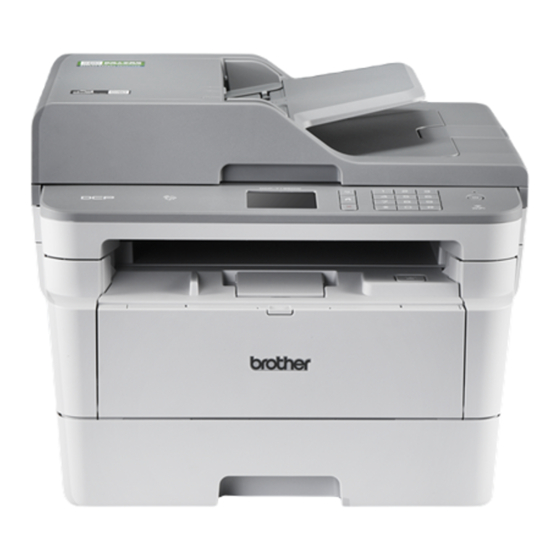
DCP-7195DW
Brother DCP-7195DW Manuals
Manuals and User Guides for Brother DCP-7195DW. We have
4
Brother DCP-7195DW manuals available for free PDF download: Service Manual, Reference Manual, Quick Setup Manual
Brother DCP-7195DW Service Manual (340 pages)
Laser MFC
Brand:
Brother
| Category:
All in One Printer
| Size: 24.73 MB
Table of Contents
Table of Contents
4
Safety Information
10
Chapter 1 Supplemental Specifications
17
General
17
Network Connectivity
25
Service Information
26
Supplies
28
Media Specifications
36
Fax (Only for the Models with Fax Function)
37
Copy
38
Scanner
40
Chapter 2 Error Indications and Troubleshooting
41
Introduction
41
Precautions
41
Checks before Commencing Troubleshooting
43
Overview
45
Cross-Section Drawing
45
Printer Part
45
Scanner Part
47
Paper Feeding
49
Printer Part
49
Scanner Part
51
Operation of each Part and Location of Parts
52
Block Diagram
54
Main Components
55
Error Indications
57
Error Codes
58
Error Message
65
LCD Models
65
Touch Panel Models
74
Communication Errors
83
Troubleshooting
87
Error Cause and Remedy
87
Troubleshooting for Paper Feeding Problems
113
No Paper Feeding from Paper Tray
113
No Paper Feeding from MP Tray
114
No Paper Feeding from Manual Feed Slot
115
Multiple Sheets of Paper Are Fed
115
Paper Becomes Wrinkled
116
Paper Is Fed at an Angle
116
Paper Curls
117
Unable to Perform 2-Sided Printing
117
Paper Jam
118
Troubleshooting for Image Defects
123
Image Defect Examples
123
Troubleshooting Image Defect
124
Troubleshooting for Software Problems
138
Unable to Receive Data
138
Troubleshooting for Network Problems
139
Cannot Make a Print through Network Connection
139
Cannot Connect to Access Point
139
Troubleshooting for Control Panel Problems
140
Nothing Is Displayed on the LCD
140
Nothing Is Displayed on the LED
140
Unable to Perform Panel Operation
140
Troubleshooting for Toner Cartridge and Drum Unit Problems
141
New Toner Not Detected
141
Toner Cartridge Not Detected
141
Toner Replacement Message Displayed on LCD Is Not Cleared
142
Drum Error
142
Drum Replacement Message Displayed on LCD Is Not Cleared
142
Troubleshooting for Fuser Unit Problems
143
Fuser Unit Failure
143
Troubleshooting for Laser Unit Problems
143
Laser Unit Failure
143
Troubleshooting for PCB Problems
144
Main PCB Failure
144
Full Memory
144
Troubleshooting for Document Feeding Problems
145
No Document Is Fed
145
Multiple Documents Are Fed
145
Document Jam
146
Document Becomes Wrinkled
147
Document Size Is Not Detected Correctly
147
Troubleshooting for Scanning Image Defect
148
Troubleshooting for Fax/Phone Problems
153
Fax Cannot be Sent
153
Fax Cannot be Received
154
Communication Error Occurs
154
Receive Buffer Full During Receiving into Memory
154
Troubleshooting for Other Problems
155
Cannot Make Print
155
Cannot Update Firmware
156
Paper Low" Message Does Not Disappear
156
Message Indicating that the Report Is Full Does Not Disappear
157
Paper Tray Cannot be Recognized
157
Chapter 3 Disassembly/Reassembly
158
Safety Precautions
158
Packing
159
Screw Catalogue
160
Screw Torque List
161
Lubrication
163
Overview of Gears
164
Harness Routing
166
Disassembly Flow Chart
179
Disassembly Procedure
180
Preparation
180
Cord Hook
182
Back Cover
183
Outer Chute ASSY
184
Front Cover ASSY / Support Flap
185
Side Cover R
188
Fuser Cover
189
Inner Chute ASSY
190
Side Cover L / Speaker Harness ASSY / Handset Holder ASSY (for Models with Handset)
191
Document Scanner Unit
194
ADF Unit (for Models with ADF)
197
ADF Unit
197
ADF Cover ASSY / Document Stopper
200
Document Sub Tray
201
Document Separate Roller ASSY
203
ADF Separation Holder ASSY
204
Second Side CIS Unit / Second Side CIS Flat Cable (Only for Models with Duplex Scanning)
205
Document Cover ASSY (for Models Without ADF)
210
Panel Unit (for Touch Panel Models)
212
Panel Unit
212
Panel PCB ASSY / NFC PCB ASSY / LCD
213
Touch Panel ASSY
214
Panel Unit (for Non-Touch Panel Models)
215
Panel Unit
215
Panel PCB ASSY
216
Lcd
217
Panel Flat Cable / First Side CIS Unit / First Side CIS Flat Cable
218
Modem Flat Cable / Modem PCB ASSY
225
Joint Cover ASSY
227
Fuser Unit
228
Low-Voltage Power Supply PCB ASSY
230
New Toner Sensor PCB ASSY
232
HVPS Flat Cable / High-Voltage Power Supply PCB ASSY
233
Fan
235
Toner Box Relay PCB ASSY (for Models with Toner Box)
236
MP Relay PCB ASSY (for MP Models)
236
Toner Box New PCB ASSY (for Models with Toner Box)
236
Laser Unit Flat Cable / Laser Unit
238
Filter
240
Wireless LAN PCB (Only for Wireless Network Models)
241
Roller Holder ASSY
242
Main PCB ASSY
243
T1 Clutch / Registration Clutch
244
Frame L Unit
247
Paper Feed Motor / Paper Feed Motor Flat Cable
250
Fuser Gear 64R/36R
252
Toner Sensor PCB ASSY (Only for Models with Toner Box)
253
Front Cover Sensor
254
Eject Sensor PCB ASSY
255
Registration Front/Rear Actuator Holder ASSY
257
Paper Feed Roller ASSY / Paper Feed Sensor PCB ASSY
260
Chapter 4 Adjusting and Updating Settings as Required after Parts Replacement
261
If You Replace the Main Pcb Assy
261
Installing Firmware (Sub Firmware and Main Firmware)
262
Checking Firmware Version
262
Installing Firmware
263
Initializing the EEPROM of the Main PCB ASSY(Function Code 01)
263
Setting by Spec, Setting Serial Number and Entering Adjusted Value of Laser Unit
264
Adjusting Touch Panel (Function Code 61)(Touch Panel Models Only)
266
Acquiring White Level Data (Function Code 55)
266
If You Replace the Low-Voltage Power Supply Pcb Assy
267
Reset Irregular Power Supply Detection Counter of the Low-Voltage Power Supply PCB (Function Code 88)
267
If You Replace the Laser Unit
268
Entering Adjusted Value of Laser Unit
269
If You Replace the Panel Unit or Panel Control Pcb
271
Adjusting Touch Panel (Function Code 61) (Touch Panel Models Only)
271
Checking LCD Operation (Function Code 12)
271
If You Replace the Adf Unit, First Side Cis Unit, Second Side Cis Unit or Document Scanner Unit
272
Acquiring White Level Data (Function Code 55)
272
Scanning and Printing Check
272
Chapter 5 Service Functions
273
Function Code
273
How to Enter Maintenance Mode
273
Method of Entering Maintenance Mode for Service Personnel
273
Method of Entering End-User Accessible Maintenance Mode
274
List of Maintenance Mode Functions
275
Details of Maintenance Mode Functions
276
Initialize EEPROM Parameters (Function Code 01, 91)
276
Transition to Shipping State (Function Code 03)
277
ADF Performance Test (Function Code 08)
278
Print Quality Test Pattern (Function Code 09)
279
Set Worker Switches (WSW) and Print Worker Switch Setting Data (Function Code 10, 11)
280
Check LCD Operation (Function Code 12)
283
Check Control Panel Key Operation (Function Code 13)
285
Display Software Version (Function Code 25)
287
Check Sensor Operation (Function Code 32)
288
Display LAN Connection Status (Function Code 33)
290
Set PC Print Functions (Function Code 43)
291
Change USB No. Return Value / Adjust Left-End Print Position
295
Adjust Upper-End Print Position
297
Change ON/OFF Setting for Lower Case Compensation
298
Change ON/OFF Setting for Fixation Strength Improvement
298
Adjust Printable Range for each Speed Level (Function Code 46)
299
Transfer Received Fax Data / Log Information (Fax Models Only) (Function Code 53)
301
Fine-Tune Scanning Position (Function Code 54)
303
Acquire White Level Data and Set CIS Scan Area (Function Code 55)
304
Check Toner Cartridge (Models with Cartridge Sensor Only) (Function Code 57)
305
Adjust Touch Panel (Function Code 61)
307
Continuous Print Test (Function Code 67)
308
Print Frame Pattern (Single-Side Printing) (Function Code 69)
312
Print Frame Pattern (Duplex Printing) (Function Code 70)
313
Test Pattern (Function Code 71)
316
Configure for Country/Region and Model (Function Code 74)
317
Print Maintenance Information (Function Code 77)
324
Check Fan Operation (Function Code 78)
326
Delete Fax Data (Function Code 79)
326
Display Machine Log Information (Function Code 80)
327
Display Machine Error Code (Function Code 82)
329
Send Communication Log Information to Telephone Line (Function Code 87)
330
Reset Irregular Power Supply Detection Counter of Low-Voltage Power Supply PCB (Function Code 88)
330
Quit Maintenance Mode (Function Code 99)
330
Other Service Functions
331
Drum Cleaning
331
Print Communication Error List
333
Resetting Drum Counter
334
Chapter 6 Wiring Diagram
335
Wiring Diagram
335
Chapter 7 Periodical Maintenance
336
Periodical Replacement Parts
336
Appendix 1 Serial Numbering System
337
Appendix 2 Deleting User Setting Information
338
Appendix 3 Installing the Maintenance Printer Driver
339
Advertisement
Brother DCP-7195DW Service Manual (119 pages)
Laser MFC
Brand:
Brother
| Category:
All in One Printer
| Size: 6.6 MB
Brother DCP-7195DW Reference Manual (21 pages)
laser all-in-one printer
Brand:
Brother
| Category:
All in One Printer
| Size: 0.74 MB
Table of Contents
Table of Contents
6
General Information
7
Control Panel Overview
7
Touchscreen LCD Overview
9
How to Navigate the Touchscreen LCD
10
Load Paper
12
Load Paper in the Paper Tray
12
Load Paper in the Multi-Purpose Tray (MP Tray)
12
Troubleshooting
13
Identify the Problem
13
Error and Maintenance Messages
14
Document and Paper Jams
15
Solutions for Wireless Connection
15
Wireless LAN Report Error Codes
15
Appendix
18
Supplies
18
Print and Scan Using Your Mobile Device
20
Advertisement
Brother DCP-7195DW Quick Setup Manual (2 pages)
Brand:
Brother
| Category:
All in One Printer
| Size: 2.06 MB
Advertisement
Related Products
Brother DCP-7180DN
Brother DCP-7190DN
Brother DCP-750CW
Brother DCP-770CW
Brother DCP-7057
Brother DCP-7070DW
Brother DCP-7055
Brother DCP-7040
Brother DCP-7045N
Brother DCP-7080
Brother Categories
Sewing Machine
All in One Printer
Printer
Label Maker
Fax Machine
More Brother Manuals
Login
Sign In
OR
Sign in with Facebook
Sign in with Google
Upload manual
Upload from disk
Upload from URL