Sign In
Upload
Manuals
Brands
Bosch Manuals
Industrial PC
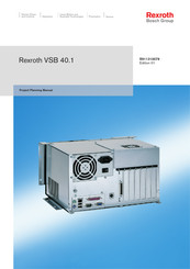
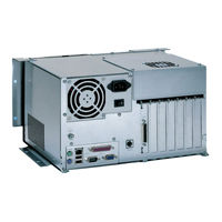
Rexroth VSB 40.1
Bosch Rexroth VSB 40.1 Manuals
Manuals and User Guides for Bosch Rexroth VSB 40.1. We have
3
Bosch Rexroth VSB 40.1 manuals available for free PDF download: Project Planning Manual
Bosch Rexroth VSB 40.1 Project Planning Manual (87 pages)
Brand:
Bosch
| Category:
Industrial PC
| Size: 3.49 MB
Table of Contents
Table of Contents
4
1 System Representation
8
Brief Description VSB 40.1
8
Operating System
8
Commissioning
9
2 Important Directions for Use
10
Appropriate Use
10
Introduction
10
Areas and Use of Application
11
Inappropriate Use
11
3 Safety Instructions for Electric Drives and Controls
12
Introduction
12
Explanations
12
Fig. 3-1: Hazard Classification (According to ANSI Z535)
12
Hazards by Improper Use
13
General Information
14
Protection against Contact with Electrical Parts
15
Protection against Electric Shock by Protective Low Voltage (PELV)
16
Protection against Dangerous Movements
17
Protection against Magnetic and Electromagnetic Fields During Operation and Mounting
18
Protection against Contact with Hot Parts
19
3.10 Protection During Handling and Mounting
19
3.11 Battery Safety
20
3.12 Protection against Pressurized Systems
20
4 Technical Data
22
PC Box
22
Fig. 4-1: Technical Data: PC Box
22
Power Supply 115 V / 230 V
23
Power Supply Unit 24 V
23
Fig. 4-2: Technical Data of the Power Supply Unit 115 V / 230
23
Fig. 4-3: Technical Data of the Power Supply Unit
23
Ambient Conditions
24
Used Standards
24
Fig. 4-4: Ambient Conditions
24
Fig. 4-5: Used Standards
24
Wear Parts
25
Fig. 4-6: Typical Operating and Storage Conditions of the Hard Disk
25
Fig. 4-7: Service Life of the Fan
25
Compatibility Check
26
5 Dimensions and Installation Notes
28
Fig. 5-1: VSB 40.1 as Variant NN
28
Fig. 5-2: VSB 40.1 as Variant LS (Drive in Connector Direction)
28
Mounting the VSB 40.1, Variant NN
29
Horizontal Mounting with Connector Panel in Forward Direction
29
Vertical Mounting with Connector Panel in Forward Direction
30
Fig. 5-5: Vertical Mounting with Connector Panel in Forward Direction
30
Fig. 5-6: Mounting Specifications for Vertical Mounting with Connector Panel in Forward Direction
30
Mounting with Connector Panel on the Top Side
31
Mounting the VSB 40.1, Variant LS
32
Mounting with Connector Panel in Forward Direction
32
Fig. 5-9: Mounting with Connector Panel in Forward Direction
32
Installation Notes
33
6 Display and Operating Components
34
Power Button
34
Display, Monitor and Keyboard
34
Display
34
VGA Monitor
34
Selection of the Graphic Driver
34
Fig. 6-1: Intel Extreme Graphics
35
Fig. 6-2: Graphics Properties
35
Fig. 6-4: Confirm Desktop Change
36
Fig. 6-5: "Hot Keys
37
7 PC Box
38
View on the Connector Panel
38
Fig. 7-1: Position of Connections of both the Different Designs
38
Interfaces
39
Overview
39
Serial Interface XCOM
40
Settings of the Serial Interface
40
Fig. 7-3: Pin Assignment COM
40
Parallel Interface XLPT
41
Fig. 6-3: "Devices
41
Fig. 7-4: LPT Interface
41
XUSB Interfaces
42
Fig. 7-5: USB Interfaces
42
Ethernet Interface XLAN
43
XVGA Interface
43
Fig. 7-6: Ethernet Interface XLAN
43
Fig. 7-7: VGA Interface
44
Keyboard Interface XKB
45
Mouse Interface Xmouse
45
Fig. 7-8: Keyboard Interface
45
Fig. 7-9: Mouse Interface XMS
45
G4 Display Interface X71
46
PC Power Supply
47
Fig. 7-10:Connection Terminal for the 24 VDC Supply
47
Fig. 7-11:Technical Data 24 VDC Connection
47
Fig. 7-12:Safety Transformer According to en 60742
48
Fig. 7-16:Technical Data 115/230 VAC Connection
50
Optional Serial Interfaces
52
CFG-VSN01E1-NN-NN-NN-NN-NN-S3 Serial Interface RS232
52
Fig. 7-18:Pin Assignment RS232, D-Sub Male Connector, 9-Pin
52
Fig. 7-20:Pin Assignment RS232, D-Sub Male Connector, 9-Pin
53
Fig. 7-21:Pin Assignment RS232, D-Sub Male Connector, 9-Pin
53
Fig. 7-23:Pin Assignment RS232, D-Sub Male Connector, 9-Pin
54
Fig. 7-24:Pin Assignment RS 422, D-Sub Male Connector, 9-Pin
54
Fig. 7-26: Position of the Connections and the Jumper on the Motherboard Variants
55
Fig. 7-27:Jumper Positions for Termination Settings
55
Fig. 7-28:Pin Assignment RS232, D-Sub Male Connector, 9-Pin
56
Fig. 7-29:Pin Assignment RS422 (here the Rexroth Standard Assignment)
56
Fig. 7-32:Jumper Positions for Termination Settings
57
8 Maintenance and Installation
58
General Information
58
CMOS Battery
58
Connection of the Uninterruptibe Power Supply
59
Mounting the UPS
59
Fig. 8-1: Connection of the UPS
59
Fig. 8-2: View of the UPS Inserted in the Holder
59
Hard Disk
60
Fig. 8-3: Installation Dimensions UPS Holder
60
Fig. 8-4: Loosen the Fastening Screws at the Mounting Frame
61
Fig. 8-5: Fastening Screws of the Hard Disk Frame
62
Fig. 8-6: Lifted Hard Disk Frame
62
Fig. 8-7: Loosen the Fastening Screws at the Mounting Frame
63
Fig. 8-8: Loosen the VSB 40.1 from the Mounting Plate
63
Fig. 8-10:Loosen the Cable from the Hard Disk
64
Fig. 8-11:Loosen the Fastening Screws of the Hard Disk
65
Fig. 8-12: Location of the Hard Disk with Damper
66
Extension Cards
67
Insert an Extension Card
67
Fig. 8-14:Loosen the Fastening Screws of the Cover
67
Fig. 8-15:Lift the Cover with Fan
68
Fig. 8-16:Remove Extension Card
68
BIOS Settings
69
Fig. 8-17:Fix the New PCI Card with the Screw
69
9 Software
70
UPS Software
70
Touch Screen Software
70
Fig. 9-1: UPDD Setup Programs for the Touch Screen
70
Fig. 9-2: Dialog Window to Set the Touch Screen
71
10 Disposal and Environmental Protection
72
10.1 Disposal
72
Products
72
Packaging Materials
72
10.2 Environmental Protection
72
No Release of Hazardous Substances
72
Materials Contained in the Products
72
Recycling
73
11 Ordering Information
74
11.1 Type Code Designation VSB40.1
74
11.2 Accessories
75
Network Connection
75
Connecting Cables to the VDP 16 and VDP 40 (G4 Display Interface)
75
Uninterruptible Power Supply
75
List of Figures
76
13 Index
80
14 Service and Support
84
14.1 Helpdesk
84
14.2 Service Hotline
84
14.3 Internet
84
14.4 Helpful Information
84
Advertisement
Bosch Rexroth VSB 40.1 Project Planning Manual (80 pages)
Brand:
Bosch
| Category:
Industrial PC
| Size: 3.83 MB
Table of Contents
Table of Contents
3
1 System Presentation
7
Brief Description VSB 40.1
7
Operating System
7
Commissioning
8
2 Important Directions for Use
9
Appropriate Use
9
Introduction
9
Areas of Use and Application
10
Inappropriate Use
10
3 Safety Instructions for Electric Drives and Controls
11
Introduction
11
Explanations
11
Fig. 3-1: Hazard Classification (According to ANSI Z535)
11
Hazards by Improper Use
12
General Information
13
Protection against Contact with Electrical Parts
14
Protection against Electric Shock by Protective Low Voltage (PELV)
15
Protection against Dangerous Movements
16
Protection against Magnetic and Electromagnetic Fields During Operation and Mounting
17
Protection against Contact with Hot Parts
18
3.10 Protection During Handling and Mounting
18
3.11 Battery Safety
19
3.12 Protection against Pressurized Systems
19
4 Technical Data
21
PC Box
21
Fig. 4-1: Technical Data: PC Box
21
Power Supply 115 V / 230 V
22
Power Supply Unit 24 V
22
Fig. 4-3: Technical Data of the Power Supply Unit
22
Ambient Conditions
23
Used Standards
23
Fig. 4-4: Ambient Conditions
23
Fig. 4-5: Used Standards
23
Wear Parts
24
Fig. 4-6: Typical Operating and Storage Conditions of the Hard Disk
24
Fig. 4-7: Service Life of the Fan
24
Compatibility Test
25
5 Dimensions and Installation Notes
27
Fig. 5-1: VSB 40.1 as Variant NN
27
Fig. 5-2: VSB 40.1 as Variant LS (Drive in Connector Direction)
27
Mounting the VSB 40.1, Variant NN
28
Mounting with Connector Panel in Forward Direction
28
Fig. 5-3: Connector Panel in Forward Direction, Optional Drive at the Top
28
Fig. 5-4: Dimension When Mounting the Connector Panel in Forward Direction
28
Mounting with Connector Panel on the Top Side
29
Mounting the VSB 40.1, Variant LS
30
Mounting with Connector Panel in Forward Direction
30
Fig. 5-7: Mounting with Connector Panel in Forward Direction
30
Fig. 5-8: Dimension When Mounting the Connector Panel in Forward Direction
30
Installation Notes
31
6 Display and Operating Components
33
Power Button
33
Display, Monitor and Keyboard
33
Display VDP
33
VGA Monitor
33
Selection of the Graphic Driver
33
Fig. 6-1: Intel Extreme Graphics
34
Fig. 6-2: Graphics Properties
34
Fig. 6-3: "Devices" Tab
34
Fig. 6-4: Confirm Desktop Change
35
Fig. 6-5: "Hot Keys" Tab
36
7 PC Box
37
View on the Connector Panel
37
Interfaces
37
Overview
37
Serial Interface XCOM
38
Settings of the Serial Interface
38
Fig. 7-3: Pin Assignment COM
38
Parallel Interface XLPT
39
Fig. 7-4: LPT Interface
39
XUSB Interfaces
40
Fig. 7-5: USB Interfaces
40
Ethernet Interface XLAN
41
XVGA Interface
41
Fig. 7-6: Ethernet Interface XLAN
41
Fig. 7-7: XVGA Interface
42
Keyboard Interface XKB
43
Mouse Interface Xmouse
43
Fig. 7-8: Keyboard Interface
43
Fig. 7-9: Mouse Interface XMS
43
GIGASTAR Interface X71
44
PC Power Supply
45
Fig. 7-12: Safety Transformer According to en 60742
46
Fig. 7-13: Illustration of the Limit Values for the 24 VDC Voltage
46
Fig. 7-15: Pin Assignment of the 230/115 VAC Connection X20
48
Fig. 7-16: Technical Data 115/230 VAC Connection
48
8 Maintenance and Installation
51
General Information
51
CMOS Battery
52
Connection of the Uninterruptibe Power Supply
52
Mounting the UPS
52
Fig. 8-1: Connection of the UPS
52
Fig. 8-2: View of the UPS Inserted in the Holder
52
Hard Disk
53
Fig. 8-4: Fastening Screws of the Hard Disk Frame
54
Fig. 8-5: Lifted Hard Disk Frame
55
Fig. 8-3: Loosen the Fastening Screws at the Mounting Frame
56
Fig. 8-7: Loosen the VSB 40.1 from the Mounting Plate
56
Fig. 8-8: Tip the VSB 40.1 to the Left and Remove It from the Mounting Plate
57
Fig. 8-9: Loosen the Cable from the Hard Disk
57
Fig. 8-10: Loosen the Fastening Screws of the Hard Disk
58
Extension Cards
59
Insert an Extension Card
59
Fig. 8-11: Loosen the Fastening Screws of the Cover
59
Fig. 8-12: Lift the Cover with Fan
60
Fig. 8-13: Remove the Slot Plate
60
BIOS Settings
61
Fig. 8-14: Fix the New PCI Card with the Screw
61
9 UPS Software
63
Fig. 9-1: Icon of the UPS Software in the Task Bar
63
10 Ordering Information
65
10.2 Accessories
66
Network Connection
66
Connecting Cables to the VDP 16.1, VDP 40.1 and VDP 60.1 (GIGASTAR Interface)
66
Uninterruptible Power Supply
66
Storage Media
66
11 List of Figures
67
12 Index
69
13 Service & Support
73
13.1 Helpdesk
73
13.2 Service-Hotline
73
13.3 Internet
73
Vor der Kontaktaufnahme
73
13.5 Kundenbetreuungsstellen
74
Sales & Service Facilities
74
Bosch Rexroth VSB 40.1 Project Planning Manual (86 pages)
Control Cabinet PC
Brand:
Bosch
| Category:
Desktop
| Size: 4.68 MB
Table of Contents
Table of Contents
3
1 System Presentation
7
Brief Description VSB 40.1
7
Operating System
7
Commissioning
8
2 Important Instructions for Use
9
Appropriate Use
9
Introduction
9
Areas of Use and Application
9
Inappropriate Use
10
3 Safety Instructions for Electric Drives and Controls
11
Definitions of Terms
11
General Information
12
Using the Safety Instructions and Passing Them on to Others
12
Requirements for Safe Use
12
Hazards by Improper Use
13
Instructions with Regard to Specific Dangers
15
Protection against Contact with Electrical Parts and Housings
15
Protective Extra-Low Voltage as Protection against Electric Shock
16
Protection against Dangerous Movements
16
Protection against Magnetic and Electromagnetic Fields During Operation and Mounting
18
Protection against Contact with Hot Parts
18
Protection During Handling and Mounting
19
Battery Safety
19
Protection against Pressurized Systems
20
Explanation of Signal Words and the Safety Alert Symbol
20
4 Technical Data
23
PC Box
23
Power Supply Unit 115 V / 230 V
23
Voltage Supply
24
Ambient Conditions
25
Used Standards
25
CE Marking
26
Declaration of Conformity
26
Note for the Machine Manufacturer
26
UL and CSA Certified
26
Wear Parts
27
Compatibility Test
28
5 Dimensions and Installation Notes
29
General Information
29
Mounting the VSB 40.1 Variant NN
30
Horizontal Mounting with Connector Panel in Forward Direction
30
Vertical Mounting with Connector Panel in Forward Direction
31
Mounting with Connector Panel on the Top Side
33
Mounting the VSB 40.1 Variant LS
34
Mounting with Connector Panel in Forward Direction
34
Installation Notes
34
6 Display and Operating Components
37
Power Button
37
Display, Monitor and Keyboard
37
Display
37
VGA Monitor
37
Selecting the Graphics Driver
37
7 PC Box
41
View on the Connector Panel
41
Interfaces
41
General Information
41
Overview
42
Serial Interface XCOM
42
Settings of the Serial Interface
43
Parallel Interface XLPT
43
XUSB Interfaces
44
Ethernet Interface XLAN
45
XVGA Interface
46
Keyboard Interface XKB
47
Mouse Interface Xmouse
47
G5 Display Interface X71
48
PC Voltage Supply
49
Optional Serial Interfaces
53
General Information
53
CFG-VSN01E1-NN-NN-NN-NN-NN-S3 Serial Interface RS232
53
XCOM4 on Slot for A6 Extension Card
53
CFG-VSN01E1-NN-NN-NN-NN-S3-S3 Serial Interfaces RS232
54
XCOM3 on Slot for A5 Extension Card
54
XCOM4 on Slot for A6 Extension Card
55
CFG-VSN01E1-NN-NN-NN-NN-NN-S2 Serial Interfaces RS232 and RS422
55
XCOM4 on Slot for A6 Extension Card
56
Jumper Setting on the Motherboard
56
CFG-VSN01E1-NN-NN-NN-NN-NN-S6 Serial Interfaces RS232 and RS422 (Rexroth Standard)
57
XCOM4 on Slot for A6 Extension Card
57
XCOM4 on Slot for A6 Extension Card
58
Jumper Setting on the Motherboard
59
8 Maintenance and Installation
61
General Information
61
CMOS Battery
61
Connecting the Uninterruptible Power Supply (UPS)
61
Mounting the UPS
62
General Information
62
Dimensions of the UPS
63
Hard Disk
63
General Information
63
Exchanging the Hard Disk of the VSB 40.1, NN Variant
64
Exchanging the Hard Disk of the VSB 40.1, LS Variant
66
Exchanging Hard Disk with Damper
68
Extension Cards
69
General Information
69
Inserting Extension Card
69
BIOS Settings
72
9 Software
73
UPS Software
73
Touch Screen Software
73
10 Environmental Protection and Disposal
75
Environmental Protection
75
Disposal
75
11 Ordering Information
77
Type Designation Code VSB 40.1
77
Accessories
79
Power Supply
79
Connecting Cables to VDP 16 and VDP 40 (G4/G5 Display Interface)
79
Uninterruptible Power Supply (UPS)
79
12 Service and Support
81
Index
83
Advertisement
Advertisement
Related Products
Bosch VSB40.1G4E-512NN-C1C-AE-LS-FW
Bosch Rexroth lndraControl VPB 40.1
Bosch Rexroth IPC 40.2
Bosch VSS8394/01T
Bosch VSS7390/01T
Bosch VS79015T
Bosch VS79055T
Bosch VS79155T
Bosch VSS7915/00T
Bosch VSS7901/00T & VS79015T
Bosch Categories
Dishwasher
Washer
Oven
Power Tool
Dryer
More Bosch Manuals
Login
Sign In
OR
Sign in with Facebook
Sign in with Google
Upload manual
Upload from disk
Upload from URL