Sign In
Upload
Manuals
Brands
ABB Manuals
Inverter
PVS800-57B
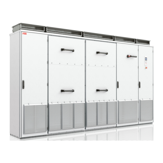
ABB PVS800-57B Manuals
Manuals and User Guides for ABB PVS800-57B. We have
2
ABB PVS800-57B manuals available for free PDF download: Hardware Manual, Maintenance Manual
ABB PVS800-57B Hardware Manual (84 pages)
Solar Central Inverters
Brand:
ABB
| Category:
Inverter
| Size: 8.54 MB
Table of Contents
Table of Contents
5
1 Safety Instructions
9
Contents of this Chapter
9
Use of Warnings
9
Installation and Maintenance Safety
10
Electrical Safety
10
Performing Electrical Work
12
General Safety
14
Safe Start-Up and Operation
15
2 Introduction to the Manual
17
Contents of this Chapter
17
Applicability
17
Target Audience
17
Contents of the Manual
18
Related Documents
18
Categorization by Frame Size and Option Code
18
Terms and Abbreviations
19
3 Operation Principle and Hardware Description
21
Contents of this Chapter
21
Product Overview
21
Block Diagram of a Solar Generator System
22
Simplified Main Circuit Diagram
23
Layout Overview
24
Overview of Power and Control Connections
26
Type Designation Labels
27
Inverter Label
27
Type Designation Key
28
Basic Code
28
Inverter Module Label
28
Option Codes
29
4 Planning the Mechanical Installation
31
Contents of this Chapter
31
Safety
31
Unpacking and Checking the Installation Site
31
Planning the Mounting of the Inverter
31
5 Planning the Electrical Installation
33
Contents of this Chapter
33
Limitation of Liability
33
Selecting the Transformer
33
Requirements for the Transformer
34
Selecting the Grid Disconnecting Device
35
Selecting the DC Input Disconnecting Device
35
Compatibility of the Solar Generator and Inverter
35
Selecting the Power Cables
36
General Rules
36
Sufficient Shield Conductivity to Suppress Emissions
37
Recommended AC Output Power Cable Types
37
Not Allowed AC Output Power Cable Types
38
Typical DC Input Power Cable Sizes
38
Typical AC Output Power Cable Sizes
38
Selecting the Control Cables
39
Signals in Separate Cables
39
Signals Allowed to be Run in the same Cable
39
Relay Cable Type
39
Routing the Cables
40
Separate Control Cable Ducts
40
Protecting in Short-Circuit Situation and against Thermal Overload
41
Protecting the Inverter and AC Output Cable in Short-Circuit Situations
41
Protecting the Photovoltaic Generator and DC Input Cable in Short-Circuit Situations
41
Protecting the Inverter and the AC Output Cable against Thermal Overload
41
Protecting the DC Input Cable against Thermal Overload
41
Protecting against Ground Faults in the DC Input Cable or Solar Generator
42
Insulation Monitoring Device
42
Protecting the Contacts of Relay Outputs
43
Inverters Without Input DC Fuses (Option +0F291)
44
6 Technical Data
45
Contents of this Chapter
45
Ratings
46
Derating
47
Temperature Derating
47
Altitude Derating
48
Fuses
49
DC Input Fuse Recommendations
50
Free Space Requirements
52
Cooling Data
52
Terminal and Lead-Through Data for the AC Power Connections
52
Terminal and Lead-Through Data for the DC Power Connections
52
Terminal and Lead-Through Data for the Control Cables
53
AC Output Connection Specification
53
DC Input Connection Data
54
Efficiency
55
Auxiliary Power Supply Data
55
3-Phase Fused Output from the Mains +G429
55
Control Unit Connection Data (BCU-12)
55
Control Panel Type
55
Protection Classes
55
Ambient Conditions
57
Materials
57
Applicable Standards
59
CE Marking - Pending
59
Compliance with the European Low Voltage Directive
59
Compliance with the European EMC Directive
59
EN55011:2016 - Pending
59
Disclaimers
60
Generic Disclaimer
60
Cybersecurity Disclaimer
60
7 Dimension Drawings
61
Contents of this Chapter
61
Cabinet Dimensions
62
Cabinet Attachment Points
64
AC and DC Cabling Lead-Throughs
66
AC Cabling
68
DC Cabling
70
8 Control Unit
73
Contents of this Chapter
73
BCU Control Unit
73
Layout and Connections
74
Ac500 Plc
75
Abb Pm564
76
Abb Ai523
77
Abb Ai561
78
Abb Dx571
79
Default I/O Connection Table
80
Bcu-12 (A41)
80
AC500 Module PM564-RP (A500)
80
AC500 Module AI523 #1 (A510)
81
AC500 Module AI523 #2 (A511)
81
AC500 Module AI561 #1 (A520)
81
AC500 Module AI561 #2 (A521)
82
AC500 Module DX572 #1 (A530)
82
AC500 Module DX572 #3 (A531)
82
Further Information
83
Advertisement
ABB PVS800-57B Maintenance Manual (78 pages)
central inverters
Brand:
ABB
| Category:
Inverter
| Size: 10.87 MB
Table of Contents
Table of Contents
5
1 Safety Instructions
9
Contents of this Chapter
9
Use of Warnings
9
Installation and Maintenance Safety
10
Electrical Safety
10
Performing Electrical Work
12
General Safety
14
Safe Start-Up and Operation
15
2 Introduction to the Manual
17
Contents of this Chapter
17
Applicability
17
Target Audience
17
Contents of the Manual
18
Related Documents
18
Categorization by Frame Size and Option Code
18
Quick Installation, Commissioning and Operation Flowchart
19
Terms and Abbreviations
20
3 Storing, Lifting and Transporting
23
Contents of this Chapter
23
Moving the Inverter
23
Storing the Inverter
24
Lifting the Inverter in the Shipping Package
25
With a Crane
25
With a Forklift Truck
26
Moving the Crate with a Forklift
27
Transporting the Inverter
28
4 Mechanical Installation
29
Contents of this Chapter
29
Safety
29
Required Tools
29
Unpacking
29
Examining the Delivery
30
Examining the Installation Site
30
Moving the Unpacked Inverter Cabinet
31
Fastening the Cabinet to the Floor and Wall or Roof
33
General Rules
33
Fastening Methods
34
Clamping
34
Miscellaneous
35
Cable Duct in the Floor below the Cabinet
35
Ventilation
35
Preventing the Recirculation of Hot Air
36
Ventilation Duct at the Air Outlet of the Cabinet
36
5 Electrical Installation
39
Contents of this Chapter
39
Insulation Test
39
Inverter
39
AC Output Cables
39
PV Generator
39
Routing the Cables
40
Connecting the Power Cables
41
Connection Diagram
41
Connection Diagram of a Four-Conductor System
42
DC Input Cable Connection Procedure
43
AC Output Cable Connection Procedure
44
Checking the Settings of the Auxiliary Voltage Transformer
45
3-Phase Power Output (Optional)
45
Connecting the Control Cables
46
Default I/O Connection Diagram
46
Connection Procedure
46
Fast Power off Circuit
47
Startup after FPO
47
Connecting a PC
48
Installing Fieldbus Adapter Modules
49
6 Installation Checklist
51
Contents of this Chapter
51
Warnings
51
Checklist
52
7 Start-Up and Operation
53
Contents of this Chapter
53
Start-Up Procedure
53
Safety
53
Primary and Ambient Conditions
53
Set up the Insulation Monitoring Device
54
Set-Up the Current Transducers (Option +G417) for All DC Inputs
54
Hints on Using the Assistant Control Panel
54
Parameter Settings before the First Start
54
First Start
54
Starting and Stopping the Inverter
55
Set up Fieldbus Control
55
Register the Inverter
55
8 Hardware Status
57
Contents of this Chapter
57
Leds
57
Warning and Fault Messages
58
9 Maintenance
59
Contents of this Chapter
59
Maintenance Intervals
59
Descriptions of Symbols
59
Recommended Annual Maintenance Actions by the User
60
Recommended Maintenance Intervals
60
Maintenance Tasks
61
Examining the Environment
61
Cleaning the Cabinet
61
Replacing the Cabinet Door Air Filters and Cleaning the Grilles
62
Fans
63
Replacing the Power Module Cooling Fans
63
Replacing the Power Module Board Compartment Fan
64
Replacing the LCL Filter Cooling Fans
65
Replacing the AUX Cabinet Cooling Fan
66
Replacing the DC Cabinet Cooling Fans
67
Replacing the AC Cabinet Cooling Fans
68
Replacing the Inverter Power Module
69
Procedure
69
Heat Sink Cleaning
73
Memory Unit
74
Replacing the BCU Control Unit Battery
74
Replacing the Control Panel Battery
74
Spare Parts
74
Storing Spare Parts
74
DC Circuit Capacitors Reforming, Spare Modules, and Spare Capacitors
75
Further Information
77
Advertisement
Related Products
ABB PVS800-57-0100kW-A
ABB PVS800-57-0875kW-B
ABB PVS800-57-1000kW-C
ABB PVS800-57-0250kW-A
ABB PVS800-57-0315kW-B
ABB PVS800-57-0500kW-A
ABB PVS800-57-0630kW-B
ABB PVS800-IS
ABB PVS-100-TL-2400
ABB Fimer PVS980-58-5000kVA-L
ABB Categories
Industrial Equipment
Controller
Measuring Instruments
Battery Charger
DC Drives
More ABB Manuals
Login
Sign In
OR
Sign in with Facebook
Sign in with Google
Upload manual
Upload from disk
Upload from URL