Sign In
Upload
Manuals
Brands
ABB Manuals
Measuring Instruments
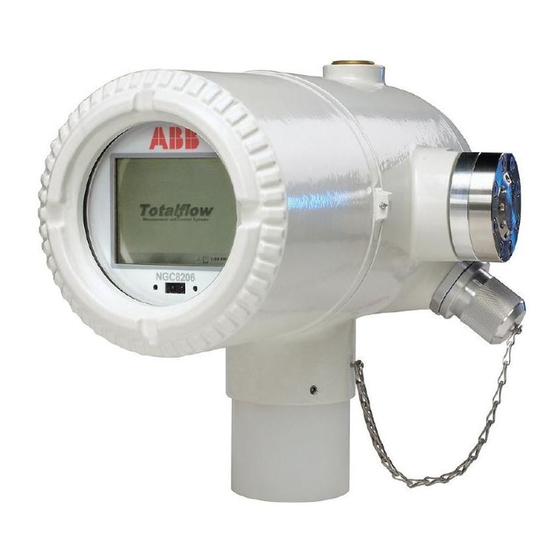
NGC8206
ABB NGC8206 Manuals
Manuals and User Guides for ABB NGC8206. We have
2
ABB NGC8206 manuals available for free PDF download: User Manual, Startup Manual
ABB NGC8206 User Manual (239 pages)
Chromatograph
Brand:
ABB
| Category:
Measuring Instruments
| Size: 8.97 MB
Table of Contents
Table of Contents
3
1 Introduction
16
Chapter Descriptions
16
Getting Help
16
Before Calling
17
Key Symbols
17
Safety Practices and Precautions
17
Safety Guidelines
17
Safety First
18
Equipment Markings
18
Grounding the Product
18
Operating Voltage
18
Danger from Loss of Ground
19
Safe Equipment
19
Compliance
19
2 System Description
20
System Overview
20
Framework
20
Calibration
20
Typical Installation
20
Figure 2-1 Typical Single Stream Installation
21
Figure 2-2 Typical Multi-Stream Installation
22
Processing a Sample
23
Hydrocarbons
23
Table 2-1 Hydrocarbons
23
Hardware System Specifications
24
Table 2-2 System Specifications
24
Figure 2-3 Modular Design NGC8206
25
NGC8206 Standard Hardware Features
25
Cast Aluminum Enclosure
26
Recommended Spare Parts
26
Figure 2-4 NGC8206 Enclosure
27
Figure 2-5 NGC8206 Enclosure Left Side
27
Feed-Through Assembly
28
Figure 2-6 NGC8206 Enclosure Right Side
28
Figure 2-7 NGC8206 Enclosure Underside
28
Analytical Module
29
Figure 2-8 NGC Feed-Through Assembly (2102026-XXX)
29
Figure 2-9 Analytical Module
30
Figure 2-10 Manifold Assembly
31
Figure 2-11 Analytical Processor Assembly
32
Figure 2-12 GC Module Assembly
32
Digital Controller Assembly with VGA Display
33
Figure 2-13 Digital Controller Assembly with Display
33
Figure 2-14 NGC VGA Display Screen
34
Figure 2-15 Termination Panel
35
Termination Panel
35
Grounding the NGC
36
Figure 2-16 NGC Grounding Considerations
36
Other Considerations
37
Power Supply
37
Sample Probe
37
Calibration/Validation Stream
37
Table 2-3 Calibration Gas Blend Recommended Components
37
Operating Voltages and Cable Lengths
38
Table 2-4 12 VDC Battery Power Supply System Maximum Cable Lengths
39
Table 2-5 AC Power Supply System Maximum Cable Lengths
39
Sample Transport Tubing Design
40
Tube Quality
40
Calculation
40
Analysis Time
40
Transit Volume
40
Gas Volume in Transit Tubing
41
Mole
41
Maintaining Phase
41
Table 2-6 Internal Volume of Commonly Used Sample Transport Tubing
41
Heat Tracing Sample Lines
42
Tube Corrosion
42
Tube Preparation
42
Calculating Lag Time
42
Figure 2-17 Heat Tracing Sample Line
42
Calculating Using Actual Pressure
43
Calculations
43
Figure 2-18 Typical Sample Installation Diagram
43
NGC8206 Standard Software Features
44
Audit Quality Data
44
Tri-Level Security
44
Compressibility Options
44
Calculation Options
45
Engineering Units
45
Supported Protocols
45
PCCU Local Communication Options
45
Table 2-7 Calculation File Settings
45
NGC Start-Up Diagnostics
46
Carrier Pressure Regulator Tests
46
Oven Temperature Test
46
Processor Control Test
46
Stream Test
46
Table 2-8 Communication Option Comparison
46
Start-Up Wizard
47
Wizard
47
Historical Data
47
Retaining Data
47
Analysis Cycles
47
Stream Averages
47
Diagnostic Reports
47
Audit Logs
48
TCR Sample Probe (Optional Equipment)
48
Figure 2-19 Temperature Compensated Regulator with Sample Probe
48
Table 2-9 Optional Temperature Compensated Regulator (TCR)
48
Location
49
Other Considerations
49
Environmental Enclosure (Optional Equipment)
49
Standard Features
49
Figure 2-20 ENC82L Environmental Enclosure with Electric Heater
50
Figure 2-21 ENC82L Environmental Enclosure with Catalytic Heater
51
Figure 2-22: ENC82S Environmental Enclosure with Electric Heater
51
Optional Features
52
Sample Conditioning Modules (Optional Equipment)
52
Figure 2-23 ENC82S Environmental Enclosure with Catalytic Heater
52
Figure 2-24 Available Sample Conditioning Modules
53
Gas Types
53
Table 2-10 Sample Conditioning Module Descriptions
53
Figure 2-25 Single and Multiple Stream Sample Conditioning Assemblies
54
Mounting Brackets
54
Figure 2-26 Single Stream Conditioning Module Dimensions
55
Figure 2-27 Multiple Stream Conditioning Module Dimensions
55
Security Seal (Optional Equipment)
56
Customer Supplied Materials
56
Instructions
56
Optional Equipment Enclosure (Optional Equipment)
56
Figure 2-28 NGC End Cap Tabs for Security Seal
56
Figure 2-29 Security Wire W/ Seal
56
6200 Optional Equipment Enclosure
57
Power Supply Options (Optional Equipment)
57
12/24 VDC Solar Panel Power Pack
57
115/230 VAC UPS Power Option (24 VDC Systems Only)
58
Explosion-Proof Power Supply (Optional Equipment)
59
Figure 2-31 6800 Enclosure with 115/230 VAC UPS Power Option
59
Figure 2-32 Explosion-Proof AC Power Supply
60
3 Installation
61
Overview
61
What this Means
61
Organization
61
Locating Area for Installation
62
Figure 3-1 Basic Meter Run Installation
62
Figure 3-2 Typical Wall Shelf Mount Installation
62
Installation
63
Table 3-1 Installation Matrix
63
Unpacking and Inspection
64
Shipping Carton
64
Unpacking
65
Bill of Lading
65
Inspection
65
Damaged Components
65
Sample Probe Installation
65
Materials
65
Instructions
65
Stand Alone Installation
66
Figure 3-3 Sample Probe
66
Figure 3-4 Sample Probe Insertion
66
Instructions
67
Material Required
67
Large Free-Standing Environmental Enclosure Installation
67
Materials
67
Installation
67
Figure 3-5 ENC82L-Enclosure Stand Installation
68
Small Free-Standing Environmental Enclosure Installation
69
Materials
69
Installation
69
Figure 3-6 ENC82L-Enclosure Mounting Hardware
69
Figure 3-7 ENC82S-Enclosure Installation
70
Figure 3-8 ENC82S-Enclosure Mounting Hardware
70
Large Pipe-Mounted Environmental Enclosure Mounting Kit
71
Large Pipe Mounted Environmental Enclosure Mounting Kit
71
Optional Support Leg Kit
71
Figure 3-10 ENC82L-Mounting Hardware Installation
72
Figure 3-11 ENC82L-Adjustment Assembly
72
Figure 3-9 ENC82L-Mounting Brackets
72
Figure 3-12 ENC82L-Pipe Mount Installation
73
Figure 3-13 ENC82L-Chain Retainer Lock
73
Materials
74
Optional Support Leg Kit Installation
74
Figure 3-14 ENC82L-Optional Support Leg Overview
74
Materials
75
Small Pipe-Mounted Environmental Enclosure Mounting Kit
75
Installation
75
Small Pipe Mounted Environmental Enclosure Mounting Kit
75
Figure 3-15 ENC82S-Channel Tubing Installation
76
Figure 3-16 ENC82S-Pipe Mount Split Brackets
76
Figure 3-17 ENC82S- Pipe Mount Assembly
77
Figure 3-18 ENC82S-Pipe Mounted
77
Pipe Saddle Installation
78
Material Not Supplied
78
Instructions
78
Figure 3-19 Typical Pipe Saddle Installation
78
Shelf Installation
79
Materials
79
Instructions
79
NGC Installation
80
Materials
80
Instructions
80
Figure 3-20 Shelf Installation
80
Sample Conditioning Module Installation
81
Materials
81
Figure 3-21 NGC Mounting
81
Figure 3-22 NGC Optional Mounting Flange Pipe
81
Mounting Kits
82
Instructions
82
Figure 3-23 Sample System Mounting Kits
82
Sample Line Connections
83
Materials
83
Instructions
83
Figure 3-24 Single and Multiple Stream Sample Conditioning Assemblies
83
Figure 3-25 Sample Conditioning Module Line Connections
84
Sample Line(S) to NGC Inside of ENC82
85
Materials
85
Instructions
86
Figure 3-26 ENC82L-Environmental Enclosure Sample Boot
86
Figure 3-27 ENC82S-Environmental Enclosure Sample Boot
87
ENC82L Optional Pwr/Comm Outlet Box Assembly
88
Materials
88
Customer-Supplied Materials
88
Instructions
88
Figure 3-28 Power Communication Outlet Box Assembly
89
Figure 3-29 ENC82L Large Enclosure
90
Figure 3-30 Assembled Power/Communication Assembly
91
Figure 3-31 Power Wiring Diagram
92
Figure 3-32 Suggested RS-232 Wiring Instructions
93
Carrier/Calibration Bottle Rack Installation on Meter Run
94
Figure 3-33 Suggested RS-485 Wiring Instructions
94
Figure 3-34 Suggested RS-422 Wiring Instructions
94
Instructions
95
ENC82 Carrier Gas Bottle Rack Installation
95
Materials
95
Figure 3-35 Carrier/Calibration Gas Bottle Rack Installation
95
Figure 3-36 Dual Bottle Rack Assembly
96
Figure 3-38 ENC82S-Dual Bottle Rack Installation
97
Carrier Gas Regulator Installation
98
Materials
98
Instructions
98
Figure 3-39 Carrier Gas Pressure Regulator with Relief Valve
98
ENC82L Calibration Gas Bottle Installation
99
Materials
99
Instructions
99
Figure 3-40 Carrier Gas Low Pressure Switch Wiring Instruction
99
ENC82S Calibration Gas Bottle Installation
100
Materials
100
Instructions
100
Figure 3-41 Calibration Bottle Location
100
Calibration Gas Regulator Installation
101
Materials
101
Instructions
101
Figure 3-42 Calibration Bottle Location
101
Figure 3-43 Calibration Gas Pressure Regulator with Relief Valve
102
Carrier Gas and Calibration Gas Connections
103
Materials
103
Instructions
103
Figure 3-45 Carrier and Calibration Gas Connections
103
Vent Lines Connections
105
Materials
105
Instructions
105
Figure 3-46 Vent Line Connections on Feed-Through Assembly
105
ENC82L Optional Catalytic Heater Installation
106
Materials
106
Instructions
106
Figure 3-47 Catalytic Heater Option in Environmental Enclosure
107
Figure 3-48 Catalytic Heater Assemblies
107
Figure 3-49 Thermostat Assembly Installed
108
Figure 3-50 Regulator and Filter/Drain Assembly Installed
108
Figure 3-51 Temperature Probe Installation
109
ENC82S Optional Catalytic Heater Installation
110
Materials
110
Figure 3-52 Electrical Pre-Heater Wiring Instructions
110
Instructions
111
Figure 3-53 ENC82S Filter/Drain Assembly Installation
111
ENC82 Optional Electric Heater Installation
112
Materials
112
Figure 3-54 ENC82S Catalytic Heater Pre-Heat Wiring
112
Instructions
113
Figure 3-55 ENC82L Electric Heater Installed in Enclosure
113
Figure 3-56 ENC82S Electric Heater Installed in Enclosure
113
Figure 3-57 Electric Heater Option Wiring Instructions
114
Figure 3-58 ENC82S Electric Heater Option Wiring Instructions
114
Sealing Environmental Enclosure
115
Customer Supplied Materials
115
Instructions
115
Optional Equipment Enclosure Installation
115
6200 Optional Equipment Enclosure
115
6800 Enclosure
116
Location
116
Pipe Mount Instructions
116
Figure 3-59 6200 Enclosure Pipe-Mounting Installation
117
Figure 3-60 6700 Enclosure Pipe Mounting Installation
117
Figure 3-61 6800 Enclosure Pipe Mounting Installation
118
Wall Mount Instructions
118
Figure 3-62 6200 Enclosure Wall Mounted Installation
119
Figure 3-63 6700 Enclosure Wall Mounted Installation
119
115/230 VAC UPS Power Supply (24 VDC Systems)
120
Figure 3-64 6800 Enclosure Wall Mounted Installation
120
Instructions
121
115/230 VAC to 12 VDC Explosion-Proof Power Supply Installation
122
Figure 3-65 115/230 VAC UPS Power Supply Option
122
Customer Supplied Materials
123
Figure 3-66 Explosion-Proof AC Power Supply Top/Front Dimensions
123
Figure 3-67 Explosion-Proof AC Power Supply Side Dimensions
124
Instructions
124
110/240 VAC to 12/24 VDC Power Supply Installation
125
Figure 3-68 Explosion-Proof AC Power Supply Wiring Instructions
125
Figure 3-69 6200 Optional Equipment Enclosure with Power Supply
126
Figure 3-70 6700 Optional Equipment Enclosure with Power Supply
126
Figure 3-71 AC/DC Converter Wiring Instructions
127
Instructions
127
VDC to 12 VDC Power Converter
128
Instructions
128
Battery Pack Installation
129
Figure 3-72 24 VDC/12 VDC Power Supply Converter
129
Figure 3-73 Optional 6800 Enclosure with Battery Pack
130
Figure 3-74 12/24 VDC Dual Battery Pack Cable
130
Instructions
130
Figure 3-75 Battery Pack with DC Power Supply Wiring Instructions
131
Solar Panel Installation
132
Materials Supplied
132
Material Not Supplied
132
Figure 3-76 Battery Pack with AC Power Supply Wiring Instructions
132
Instructions
133
Solar Power Pack
133
Figure 3-77 Typical Solar Panel Installation
133
Instructions
134
Figure 3-78 12 VDC Battery Pack/Solar Panel Wiring Instructions
135
Figure 3-79 24 VDC Battery Pack/Solar Panel Wiring Instructions
136
DC Power Installation
137
Instructions
137
Remote Communication Installation
137
Table 3-2 Port 1 and Port 2 Pin-Outs/Terminations
137
4 Ngc8206 Startup
139
PCCU32 Installation and Setup
139
Software Installation Instructions
139
Ethernet Installation and Setup
140
TCP/IP Network Connection
140
Figure 4-1 Ethernet Connections
140
Figure 4-2 Ethernet Cable-Typical
141
TCP/IP Local Connection
142
Figure 4-3 Ethernet Cable-Cross-Over
142
Connecting to the NGC8206 Local Port
143
Communicate Instructions
143
NGC Diagnostics
144
Figure 4-4 MMI Communication Cables
144
NGC Start-Up Wizard
145
Station Setup Instructions
145
Table 4-1 Station Setup Screen Information
145
Stream Setup Instructions
146
Calibration Setup Instructions
146
Diagnostics
147
Update Configuration
147
Analyze Calibration Stream
147
Start-Up Completion
148
Calibrating the NGC
148
Instructions
148
Figure 4-5 Typical Chromatograph for Chrom-1 (Heavies)
149
Security System
150
Security Code
150
Hardware Security
150
Software Security
150
Figure 4-6 Typical Chromatograph for Chrom-2 (Lights)
150
Alarm Definitions
151
Table 4-3 Defaulted Alarm Definitions
151
5 Maintenance
153
Overview
153
Help
153
Maintaining Cleanliness
153
How to Use this Chapter
153
Returning Part(S) for Repair
153
Spare Part Components
154
Replacement Components
154
Replacement Parts
154
Figure 5-1 NGC8206 Overall View
155
Figure 5-2 Analytical Module, Exploded
156
Figure 5-3 Feed through Assembly, Exploded
156
Repair Time
157
Recommended Spares
157
Customer Service
157
Table 5-1 Repair Time Vs. down Time
157
Table 5-2 Recommended Spare Parts
157
Field Tool Kit
158
Visual Inspection
158
Inspection
158
Table 5-3 Tool Requirements
158
Backing up Configuration Files (Save)
159
Instructions
159
Restore Configuration Files
159
Reset Procedures
160
Warm Start Instructions
160
Cold Start Instructions
160
Restore Factory Defaults
161
Figure 5-4 Digital Controller Complete Assembly
161
Instructions
162
Lithium Battery Status
162
Changing NGC Clock
163
Clock Change Not Crossing a Log Period Boundary
163
Forward Clock Change Crossing a Log Period Boundary
163
Backward Clock Change Crossing a Log Period Boundary
163
Replacing Calibration or Carrier Gas Bottle(S)
163
Instructions
163
Removing Digital Controller Assembly
164
Instructions
164
Replacing Digital Controller Complete Assembly
165
Instructions
165
Figure 5-5 Digital Controller Board
166
Replacing Analytical Module
167
Instructions
167
Figure 5-6 Analytical Module
168
Figure 5-7 Analytical Processor Board
168
Replacing GC Module
169
Instructions
170
Figure 5-8 GC Module, Exploded View
171
Replacing Termination Panel
172
Instructions
172
Figure 5-9 Termination Panel
173
Replacing Feed-Through Assembly
174
Instructions
174
Figure 5-10 Feed-Through Assembly
175
Replacing Lithium Battery
176
Instructions
176
Replacing Frit Filters
177
Instructions
177
Figure 5-11 Primary Component Side Digital Controller Board
177
Figure 5-12 Feed-Through Assembly, Exploded View
178
Replacing Feed-Through Interface Gasket
179
Instructions
179
Replacing Feed-Through Manifold Gasket
179
Replacing Termination Panel to Digital Controller Cable
181
Instructions
181
Replacing Analytical Processor to Termination Panel Cable
182
Instructions
182
6 Troubleshooting
184
Overview
184
Troubleshooting Support
184
Getting Started
184
Start-Up Diagnostic Troubleshooting
185
Figure 6-1 Troubleshooting Flowchart
185
Carrier Pressure Regulator Test
186
Status
186
Oven Temperature Test
187
Processor Control Test
188
Stream Test
188
Troubleshooting Alarms
189
Operators
190
Table 6-1 NGC8200 Alarms
190
Alarm Severity
191
Pressure Regulator 1 or 2 Alarm
191
Table 6-2 Alarm Severity
191
Sample Pressure Alarm
192
Oven Temperature Error Alarm
193
No Stream Valve Selected
194
Digital-Analog Board Communication Error Alarm
194
Calculation Error Alarm
195
Calibration Un-Normalized Error Alarm
195
Stream Sequence Error Alarm
196
Calibration CV Percent Error Alarm
196
Calibration RF Percent Error Alarm
197
Enclosure Temperature Alarm
198
Power Supply Alarm
198
Low Carrier Gas Bottle (DI1) Alarm
199
Low Cal Gas Bottle (DI2) Alarm
199
GCM Processing Error Alarm
200
Bad Bead Alarm
200
No Pilot Valve Change Detected Alarm
200
Sample Flow Detection Alarm
201
CPU Loading Alarm
201
System Memory Available Alarm
201
RAM File Available Alarm
202
FLASH File Available Alarm
202
Missing Peak - Calibration Not Used
202
Stream Un-Normalized Total
203
Alarm Troubleshooting Tests
204
Sample Vent Pressure Test
204
Column Vent Pressure Test
204
Sample Pressure Test
204
Feed-Through Assembly Blockage Test
205
Temperature Sensor Test
205
Abnormal Calibration Gas Depletion
205
Power Troubleshooting
205
Overview
205
Power Supply Voltage Test
206
Figure 6-2 Power Troubleshooting Flowchart
206
Equipment Isolation Test
207
NGC Module Isolation Test
208
Charger Circuit Test
209
Solar Panel Troubleshooting Test
210
Table 6-3 Specifications for Solar Panels
210
AC Charger/Power Supply Troubleshooting Test
211
Troubleshooting Communications
211
Communication
212
Setting up Communication
212
Transceiver Supply Voltage Test
214
VDC Communication Supply Voltage Test
214
Transceiver Check
215
Communication Test
215
Table 6-4 RS-232 Field Wiring on NGC Termination Panel
215
Communications
216
Communication Test
217
Table 6-5 RS-485 Terminations
217
Table 6-6 RS-485 Field Wiring on NGC Termination Panel
217
Appendix Amodbus Registers
219
Contact Us
239
Advertisement
ABB NGC8206 Startup Manual (24 pages)
Brand:
ABB
| Category:
Laboratory Equipment
| Size: 1.18 MB
Table of Contents
Basic Installation
3
Remote Communication
15
Communication Troubleshooting
17
Start-Up Troubleshooting
18
Troubleshooting Solutions
21
Advertisement
Related Products
ABB NGC8200
ABB NETA-21
ABB Navigator 600 Series
ABB Navigator 500 Series
ABB Navigator 600 Phosphate
ABB NBRA-6 Series
ABB NBRA-663
ABB NBRA-664
ABB NBRA-657
ABB NMBP-01
ABB Categories
Industrial Equipment
Controller
Measuring Instruments
Battery Charger
DC Drives
More ABB Manuals
Login
Sign In
OR
Sign in with Facebook
Sign in with Google
Upload manual
Upload from disk
Upload from URL