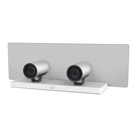
Cisco TelePresence SpeakerTrack 60 Installation Manual
Hide thumbs
Also See for TelePresence SpeakerTrack 60:
- Manual (22 pages) ,
- Installation manual (14 pages) ,
- Datasheet (3 pages)
Table of Contents
Advertisement
Quick Links
Download this manual
See also:
Manual
Advertisement
Table of Contents

Summary of Contents for Cisco TelePresence SpeakerTrack 60
-
Page 1: Installation Guide
Cisco TelePresence SpeakerTrack 60 InstallatIon guIde The SpeakerTrack 60 uses a unique dual-camera technique to quickly view a close-up of the active speaker in the meeting room. 78-100223-02C0 | MARCH 2015. Copyright © 2015 Cisco Systems, Inc. All rights reserved. -
Page 2: Installation
2 × Thumb nut, M4 4 × Pan headed screw, M4 16 mm 2 × 1/4” UNC screw 1 × Template for attaching the wall bracket (not shown) 78-100223-02C0 | MARCH 2015. Copyright © 2015 Cisco Systems, Inc. All rights reserved. -
Page 3: Safety Instructions
The installer is responsible for obtaining safety inspection of the structural integrity of the installation by the local authority/inspection department. note: Note that the surface is hot when the camera is in operation. 78-100223-02C0 | MARCH 2015. Copyright © 2015 Cisco Systems, Inc. All rights reserved. - Page 4 900 cm / 354 in Top view of a room with SpeakerTrack 60. For optimal audio tracking the SpeakerTrack should be mounted at some distance from the side walls. 78-100223-02C0 | MARCH 2015. Copyright © 2015 Cisco Systems, Inc. All rights reserved.
- Page 5 Side view of a room with SpeakerTrack 60 mounted above the monitor. For optimal audio tracking the SpeakerTrack should be mounted at some distance to the ceiling. 78-100223-02C0 | MARCH 2015. Copyright © 2015 Cisco Systems, Inc. All rights reserved.
- Page 6 The maximum depth of the recess is 217.6 mm (8.56 in). If less depth the camera will protrude from the wall. Follow local building regulations and accessibility requirements. 78-100223-02C0 | MARCH 2015. Copyright © 2015 Cisco Systems, Inc. All rights reserved.
- Page 7 Side view of a room with SpeakerTrack 60 mounted beow the monitor. For large monitors (70” and above), we recommend mounting the SpeakerTrack below the monitor. 78-100223-02C0 | MARCH 2015. Copyright © 2015 Cisco Systems, Inc. All rights reserved.
- Page 8 The maximum depth of the recess is 217.6 mm (8.56 in). If less depth the camera will protrude from the wall. Follow local building regulations and accessibility requirements. 78-100223-02C0 | MARCH 2015. Copyright © 2015 Cisco Systems, Inc. All rights reserved.
-
Page 9: Mounting The Wall Bracket
Support mural de matériau du mur (bois, ciment, gypse). 78-100272-01A0 | FEBRUARY 2014. Copyright © 2014 Cisco Systems, Inc. All rights reserved. 78-100272-01A0 | FEBRUARY 2014. Copyright © 2014 Cisco Systems, Inc. All rights reserved. 78-100223-02C0 | MARCH 2015. Copyright © 2015 Cisco Systems, Inc. All rights reserved. -
Page 10: Mounting The Base Unit
Make sure the guide-pins positions correctly. Use the four pan headed screws (P) when fastening the base unit. Use the Torx Key (M) and tighten the screws. 78-100223-02C0 | MARCH 2015. Copyright © 2015 Cisco Systems, Inc. All rights reserved. -
Page 11: Mounting The Cables
(typically if a Touch device is connected) you will need a network switch. Connect the switch to the Ethernet port on the codec, and connect the Touch device and SpeakerTrack 60 to the switch. We recommend using a Cisco switch. Connect the short Ethernet and... - Page 12 Hold and lift the unit as illustrated. Carefully place the unit onto the wall bracket. Check that the unit is level. If not, you can adjust the unit sideways. 78-100223-02C0 | MARCH 2015. Copyright © 2015 Cisco Systems, Inc. All rights reserved.
- Page 13 Place the camera (C) on a stable surface as illustrated. Use the 1/4” UNC screw (Q) and Allen Key (n) and mount the camera interface plate (e) to the camera. Repeat these steps for the second camera (C). 78-100223-02C0 | MARCH 2015. Copyright © 2015 Cisco Systems, Inc. All rights reserved.
-
Page 14: Connecting The Camera Cables
Connect the long cables (Ethernet and power) to the left camera. Connect the HDMI cable coming from the codec. Guide the camera into position. Left side Right side 78-100223-02C0 | MARCH 2015. Copyright © 2015 Cisco Systems, Inc. All rights reserved. - Page 15 Repeat this step for the second camera. Make sure the pins on the base plate fits the holes in the camera interface plate. 78-100223-02C0 | MARCH 2015. Copyright © 2015 Cisco Systems, Inc. All rights reserved.
- Page 16 Connect the Ethernet and HDMI cables to the codec, see the codec documentation for further information. • Connect the power cable to the power mains. HDMI Ethernet Power HDMI left right camera camera 78-100223-02C0 | MARCH 2015. Copyright © 2015 Cisco Systems, Inc. All rights reserved.
-
Page 17: User Documentation And Support
User documentation and support User documentation for SpeakerTrack 60: http://www.cisco.com/go/telepresence/docs Navigate to: Collaboration Endpoints > Collaboration Peripherals > TelePresence Peripherals > TelePresence SpeakerTrack 60 For support, go to: http://www.cisco.com/support 78-100223-02C0 | MARCH 2015. Copyright © 2015 Cisco Systems, Inc. All rights reserved. - Page 18 Find an overview of the Cisco offices on our web site. http://www.cisco.com/go/offices Cisco and the Cisco logo are trademarks or registered trademarks of Cisco and/or its affiliates in the U.S. and other countries. To view a list of Cisco trademarks, go to this URL: www.cisco.com/go/trademarks. Third-party trademarks mentioned are the property of their respective owners.


