Sony SA-VE502 Service Manual
Micro satellite system
Hide thumbs
Also See for SA-VE502:
- Operating instructions manual (27 pages) ,
- Operating instructions manual (27 pages)
Advertisement
SERVICE MANUAL
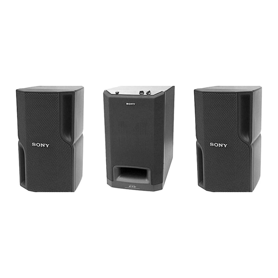
The SA-VE502 system consists of one unit
of SA-WMS5 and two units of SS-MS5.
The SA-VE505 system consists of one unit
of SA-WMS5 and five units of SS-MS5.
MICROFILM
Photo: SA-WMS5
Photo: SS-MS5
SPECIFICATIONS
SA-VE502/VE505/
WMS5/SS-MS5
Canadian Model
MICRO SATELLITE SYSTEM
US Model
AEP Model
UK Model
E Model
Advertisement
Table of Contents

Summary of Contents for Sony SA-VE502
- Page 1 US Model Canadian Model AEP Model UK Model E Model The SA-VE502 system consists of one unit of SA-WMS5 and two units of SS-MS5. The SA-VE505 system consists of one unit Photo: SA-WMS5 Photo: SS-MS5 of SA-WMS5 and five units of SS-MS5.
-
Page 2: Safety Check-Out
OPERATION. REPLACE THESE COMPONENTS WITH DE FONCTIONNEMENT. NE REMPLACER CES COM- SONY PARTS WHOSE PART NUMBERS APPEAR AS POSANTS QUE PAR DES PIÈCES SONY DONT LES SHOWN IN THIS MANUAL OR IN SUPPLEMENTS PUB- NUMÉROS SONT DONNÉS DANS CE MANUEL OU LISHED BY SONY. - Page 3 SECTION 2 SECTION 1 GENERAL DIAGRAMS • Location of Controls 2-1. NOTE FOR PRINTED WIRING BOARDS AND SCHEMATIC DIAGRAMS SA-WMS5 Note on Printed Wiring Board: Note on Schematic Diagram: – Front view – • X : parts extracted from the component side. •...
- Page 4 SA-VE502/VE505/WMS5/SS-MS5 2-2. PRINTED WIRING BOARDS • See page 4 for Circuit Boards Location. (Page 6) (Page 5) (Page 7) (Page 7) (Page 8) (Page 7) – 5 – – 6 –...
- Page 5 SA-VE502/VE505/WMS5/SS-MS5 • Semiconductor Location – MAIN Board – Ref. No. Location D101 D102 D103 B-10 D104 D105 D106 D107 D-10 D108 C-10 D303 D304 D501 D503 D504 IC101 C-10 IC102 D-10 IC301 IC302 IC303 IC501 IC502 (Page 5) (Page 6) •...
- Page 6 SA-VE502/VE505/WMS5/SS-MS5 2-3. SCHEMATIC DIAGRAM • See page 11 for IC Block Diagrams. The components identified by mark ! or dotted Les composants identifiés par une marque ! sont line with mark ! are critical for safety. critiques pour la sécurité. Ne les remplacer que Replace only with part number specified.
-
Page 7: Main Board
• IC Block Diagrams – MAIN Board – IC301 STK350-230 IC303 µPC1237HA OVER LOAD DET INPUT MUTE OFFSET DET LATCH/ AUTORESET -VEOUT AC OFF +VEOUT – AUTO POWER Board – IC602 NJM2072D INPUT OUTPUT2 GAIN CONT OUTPUT1 AMP OUT RECOVERY TIME CAP –... -
Page 8: Section 3 Exploded Views
SECTION 3 EXPLODED VIEWS NOTE: • -XX and -X mean standardized parts, so they • Items marked “*” are not stocked since they The components identified by mark ! or dotted line with mark are seldom required for routine service. Some may have some difference from the original ! are critical for safety. - Page 9 (2) AMPLIFIER SECTION (SA-WMS5) not supplied supplied T601 supplied not supplied T501 US, CND AEP, UK, G, SP, MY The components identified by Les composants identifiés par une mark ! or dotted line with marque ! sont critiques pour la mark ! are critical for safety.
- Page 10 Description Remark Ref. No. Part No. Description Remark X-4951-148-1 GRILLE ASSY, FRONT X-4951-147-1 CABINET ASSY X-4951-498-1 EMBLEM ASSY, SONY 4-986-971-11 SCREW (3.5) 4-217-715-01 SCREW (3.5X50), +P TAPPING 3-701-436-21 WASHER, POLYEHTHYLENE 4-217-295-01 PANEL, FRONT 4-220-713-01 SHEET 1-694-516-11 TERMINAL, SPEAKER SP100 1-529-292-11 SPEAKER (5cm)
-
Page 11: Section 4 Electrical Parts List
AUTO POWER SECTION 4 ELECTRICAL PARTS LIST CONTROL NOTE: • Due to standardization, replacements in the • Items marked “*” are not stocked since they The components identified by mark ! or dotted line with mark are seldom required for routine service. parts list may be different from the parts speci- ! are critical for safety. - Page 12 CONTROL MAIN Ref. No. Part No. Description Remark Ref. No. Part No. Description Remark C207 1-136-170-00 FILM 0.27uF C208 1-136-170-00 FILM 0.27uF A-4419-286-A MAIN BOARD, COMPLETE C210 1-136-177-00 FILM ********************* C211 1-136-165-00 FILM 0.1uF 1-533-233-11 HOLDER, FUSE C212 1-126-965-11 ELECT 22uF C213 1-126-965-11 ELECT...
-
Page 13: Power Board
MAIN POWER Ref. No. Part No. Description Remark Ref. No. Part No. Description Remark D103 8-719-991-33 DIODE 1SS133T-77 R301 1-249-433-11 CARBON 1/4W D104 8-719-991-33 DIODE 1SS133T-77 R302 1-249-438-11 CARBON 1/4W D105 8-719-991-33 DIODE 1SS133T-77 R303 1-249-413-11 CARBON 1/4W D106 8-719-991-33 DIODE 1SS133T-77 R304 1-249-438-11 CARBON 1/4W... -
Page 14: Power Switch Board
SA-VE502/VE505/WMS5/SS-WMS5 POWER POWER SWITCH Ref. No. Part No. Description Remark Ref. No. Part No. Description Remark Q403 8-749-010-25 IC MN2488-OPY-M ACCESSORIES & PACKING MATERIALS Q404 8-749-010-26 IC MP1620-OPY-M ******************************* < RESISTOR > 1-769-329-21 CORD, CONNECTION (PIN-PIN) 1-790-503-11 CORD, SPEAKER (2.5m)

