Advertisement
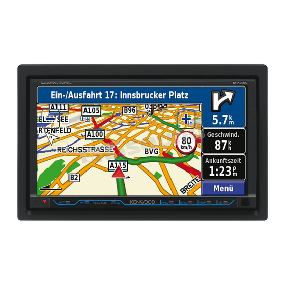
DNX7220
GPS NAVIGATION SYSTEM
INSTALLATION MANUAL
SYSTÈME DE NAVIGATION GPS
MANUEL D'INSTALLATION
GPS NAVIGATION SYSTEM
INSTALLATION-HANDBUCH
GPS NAVIGATION SYSTEM
INSTALLATIE HANDLEIDING
GPS NAVIGATION SYSTEM
MANUALE DI INSTALLAZIONE
SISTEMA DE NAVEGACIÓN GPS
MANUAL DE INSTALACIÓN
SISTEMA DE NAVEGAÇÃO GPS
MANUAL DE INSTALAÇAO
© B54-4647-00/00 (EW)
Advertisement
Table of Contents

Summary of Contents for Kenwood DNX
- Page 1 DNX7220 GPS NAVIGATION SYSTEM INSTALLATION MANUAL SYSTÈME DE NAVIGATION GPS MANUEL D’INSTALLATION GPS NAVIGATION SYSTEM INSTALLATION-HANDBUCH GPS NAVIGATION SYSTEM INSTALLATIE HANDLEIDING GPS NAVIGATION SYSTEM MANUALE DI INSTALLAZIONE SISTEMA DE NAVEGACIÓN GPS MANUAL DE INSTALACIÓN SISTEMA DE NAVEGAÇÃO GPS MANUAL DE INSTALAÇAO ©...
- Page 2 Accessories ..1 ..1 ..1 ..1 ..1 ..2 ..1 ..1 ..1 DNX7220...
-
Page 3: Installation Procedure
Installation Procedure ¤ 1. To prevent short circuits, remove the key from the ignition and disconnect the - terminal of the • Mounting and wiring this product requires skills and battery. experience. For safety’s sake, leave the mounting and wiring 2. - Page 4 A-4 Pin (Yellow) the telephone rings or during conversation. 2 The A-7 pin (red) of the vehicle’s ISO connector is To connect the Kenwood navigation system, connected to the constant power supply, and the consult your navigation manual. A-4 pin (yellow) is linked to the ignition.
-
Page 5: Rear View
Cooling fan FUSE (15A) Rear view FM/AM Antenna Cord antenna input Accessory 8 (GPS Antenna ) (see page 8) Connector A Accessory 1 Ignition wire (Red) A–7 Pin (Red) Battery wire (Yellow) A–4 Pin (Yellow) Dimmer control wire (Orange/White) ILLUMI Connector B Parking sensor wire (Light Green) Reveres sensor wire (Purple/White) -
Page 6: System Connection
System Connection USB terminal USB device (commercially available) ■ Video Input2 Resistance-free mini plug ■ Audio Input2 Resistance-free stereo type mini plug Do not connect. Accessory Accessory Accessory 4 ■ Audio/Video Output • Video output (Yellow) • Audio left output (White) •... -
Page 7: Optional Accessory Connection
Optional Accessory Connection iPod (commercially available) Audio Output (Black) Audio Input KCA-iP300V (Optional Accessory) Accessory 5 Video Output (Yellow) Video Input USB terminal USB terminal To KCA-BT200 (Optional Accessory) TV Tuner (Optional Accessory) Connection cable (Included in the TV tuner) English... -
Page 8: Installing The Gps Antenna
Installing the GPS Antenna GPS antenna is installed inside of the car. It should be installed as horizontally as possible to allow easy reception of the GPS satellite signals. To mount the GPS antenna inside your vehicle: 1. Clean your dashboard or other surface. 2. -
Page 9: Removing The Unit
Removing Monitor/Player Unit Removing the Hard Rubber Frame Removing the Unit (escutcheon) 1. Remove the hard rubber frame by referring to the removal procedure in the section <Removing the 1. Engage the catch pins on the removal tool 6 and Hard Rubber Frame>.


