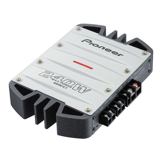
Pioneer GM-X372 Service Manual
Bridgeable power amplifier
Hide thumbs
Also See for GM-X372:
- Catalog (52 pages) ,
- Owner's manual (9 pages) ,
- Service manual (24 pages)
Table of Contents
Advertisement
Service
Manual
BRIDGEABLE POWER AMPLIFIER
GM-X372
For details, refer to "Important symbols for good services".
PIONEER CORPORATION
PIONEER ELECTRONICS (USA) INC.
PIONEER EUROPE NV
Haven 1087 Keetberglaan 1, 9120 Melsele, Belgium
PIONEER ELECTRONICS ASIACENTRE PTE.LTD. 253 Alexandra Road, #04-01, Singapore 159936
C PIONEER CORPORATION 2002
BRIDGED
GM-X372/XH/UC
4-1, Meguro 1-Chome, Meguro-ku, Tokyo 153-8654, Japan
P.O.Box 1760, Long Beach, CA 90801-1760 U.S.A.
BRIDGEABLE
2-CH POWER AMPLIFIER
XH/UC,XH/EW,XH/ES
K-ZZY. NOV. 2002 Printed in Japan
ORDER NO.
CRT3006
Advertisement
Table of Contents

Summary of Contents for Pioneer GM-X372
-
Page 1: Fuse
PIONEER ELECTRONICS (USA) INC. P.O.Box 1760, Long Beach, CA 90801-1760 U.S.A. PIONEER EUROPE NV Haven 1087 Keetberglaan 1, 9120 Melsele, Belgium PIONEER ELECTRONICS ASIACENTRE PTE.LTD. 253 Alexandra Road, #04-01, Singapore 159936 C PIONEER CORPORATION 2002 K-ZZY. NOV. 2002 Printed in Japan... -
Page 2: Safety Information
SAFETY INFORMATION - GM-X372/XH/UC CAUTION This service manual is intended for qualified service technicians; it is not meant for the casual do-it-yourselfer. Qualified technicians have the necessary test equipment and tools, and have been trained to properly and safely repair complex products such as those covered by this manual. -
Page 3: Table Of Contents
*Average current drawn • The average current drawn is nearly the maximum current drawn by this unit when an audio signal is input. Use this value when working out total current drawn by multiple power amplifiers. GM-X372/XH/UC... -
Page 4: Exploded Views And Parts List
2. EXPLODED VIEWS AND PARTS LIST 2.1 PACKING GM-X372/XH/UC... -
Page 5: Gm-X372/Xh/Uc
10 Owner’s Manual(UC) HRD0226 Owner’s Manual(EW) HRD0227 Owner’s Manual(ES) HRD0228 11 Owner’s Manual(ES) HRD0229 12 Warranty Card HRY1157 - Owner's Manual Part No. Language HRD0226 English, French HRD0227 English, French, Spanish, German, Italian, Dutch HRD0228 English, Spanish HRD0229 Portuguese(B), Arabic GM-X372/XH/UC... -
Page 6: Exterior
2.2 EXTERIOR GM-X372/XH/UC... -
Page 7: Gm-X372/Xh/Uc
PPZ30P100FZK 22 Light Pipe Unit HXA0391 23 Screw ISS30P055FUC 24 Screw PPZ30P100FZK 25 Screw HBA0029 26 FET(Q612,613,614,615) STP55NF06FP 27 Diode(D611) FML22R 28 Diode(D612) FML22S 29 Holder HNC0082 30 Screw BBZ30P080FMC 31 Screw HBA0030 32 Cushion HNM6623 33 Screw BBZ30P060FZK GM-X372/XH/UC... -
Page 8: Schematic Diagram
3.1 OVERALL CONNECTION DIAGRAM(GUIDE PAGE) Large size SCH diagram Guide page AMP UNIT Detailed page GAIN = 1 LPF SELECT GAIN = -12dB LPF SELECT EW, ES ONLY 75 H UC ONLY UC ONLY 75 H EW, ES ONLY GM-X372/XH/UC... -
Page 9: Gm-X372/Xh/Uc
Therefore, when replacing, be sure to use parts of identical designation. EW, ES ONLY R608 R609 3R3K 3R3K EW, ES 5R1K 5R1K FU602 EW, ES ONLY HEK0025 > 50 H UC ONLY GM-X372/XH/UC... -
Page 10: Gm-X372/Xh/Uc
HCS0003 HCS0003 GM-X372/XH/UC... -
Page 11: Gm-X372/Xh/Uc
GM-X372/XH/UC... -
Page 12: Gm-X372/Xh/Uc
HCS0003 HCS0003 GM-X372/XH/UC... -
Page 13: Gm-X372/Xh/Uc
RM4Z-LFJ4 GM-X372/XH/UC... -
Page 14: Pcb Connection Diagram
1.The parts mounted on this PCB include all necessary parts for several destination. For further information for respective destinations, be sure to check with the schematic dia- gram. 2.Viewpoint of PCB diagrams Capacitor Connector FU602 SIDE A SIDE B P.C.Board Chip Part SPEAKER INPUT GM-X372/XH/UC... -
Page 15: Gm-X372/Xh/Uc
SIDE A POWER SUPPLY SPEAKER OUTPUT GAIN LPF SELECT INPUT GM-X372/XH/UC... -
Page 16: Gm-X372/Xh/Uc
AMP UNIT GM-X372/XH/UC... -
Page 17: Gm-X372/Xh/Uc
SIDE B GM-X372/XH/UC... -
Page 18: Electrical Parts List
ERA15-02VH RD1/4PU472J Diode 1SS133 RD1/4PU101J L934BR235SRCF RD1/4PU221J Choke Coil 50µH (EW, ES) HTH0005 RD1/4PU152J Choke Coil 75µH (EW, ES) HTH0010 RS1/16S101J Choke Coil 75µH (EW, ES) HTH0010 RS1/16S102J Ferri-Inductor CTF1007 RS1/16S473J Ferri-Inductor CTF1007 RS1/16S102J Transformer HTT0015 RS1/16S153J Thermistor HCX0001 GM-X372/XH/UC... -
Page 19: Adjustment
RD1/4PU331J CEAT100M16 RD1/4PU331J CEAT100M16 CQMA472J50 CAPACITORS CQMA472J50 CFTNA274J50 CCSRCH470J50 CFTNA274J50 CCSRCH470J50 CFTNA154J50 CCSRCH470J50 CFTNA154J50 CCSRCH470J50 CEAT100M16 CFTNA103J50 CEAT100M16 CFTNA103J50 CEAT220M50 CEAT100M16 CEAT220M50 CEAT100M16 CEAT101M50 220µF/10V HCH0012 CEAT101M50 6. ADJUSTMENT There is no information to be shown in this chapter. GM-X372/XH/UC... -
Page 20: General Information
Remove the eight screws. Remove the screw and then remove the two Panels. Remove the four screws and then remove the two Heat Sinks. Remove the four screws and then remove the Amp Unit. Heat Sink Panel Amp Unit Heat Sink Fig.1 GM-X372/XH/UC... -
Page 21: Connector Function Description
7.1.2 CONNECTOR FUNCTION DESCRIPTION - GM-X372/XH/UC 6.5V 0.2V BRIDGED BRIDGEABLE 2-CH POWER AMPLIFIER GM-X372/XH/UC... - Page 22 7.2 IC *TDA7294V MUTE THERMAL STBY SHUTDOWN PROTECTION IC's marked by * are MOS type. Be careful in handling them because they are very liable to be damaged by electrostatic induction. GM-X372/XH/UC...
-
Page 23: Operations
8. OPERATIONS GM-X372/XH/UC... -
Page 24: Connection Diagram
If the car stereo does not have a system remote control ter- minal, connect the male terminal to the power terminal through the ignition switch. GM-X372/XH/UC...


