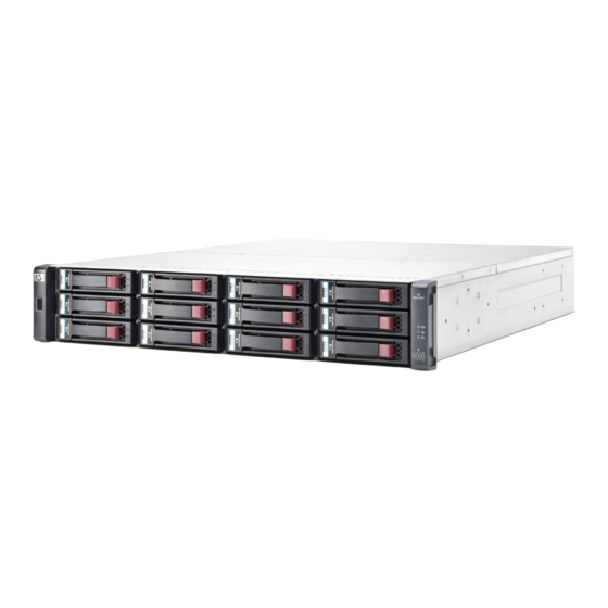
HP MSA 2040 Installation Instructions
Controller module
Hide thumbs
Also See for MSA 2040:
- User manual (100 pages) ,
- Quickspecs (35 pages) ,
- Troubleshooting manual (30 pages)
Advertisement
Quick Links
HP MSA Controller Module
Installation Instructions
Abstract
This document details procedures for installing a controller
module in HP MSA enclosures.
© Copyright 2009, 2013 Hewlett-Packard Development Company, L.P.
Printed in the US.
HP Part Number: 590339-005
Published: June 2013
Edition: 5
*590339-005*
About this document
The Storage Management Utility (SMU) and the
Command Line Interface (CLI) can be used to
manage the enclosure. Tasks in this document
demonstrate using the SMU.
For the latest product documentation, see the HP
website at http://www.hp.com/support/manuals.
Under the storage banner, navigate to the page
for your storage enclosure.
Before you begin
Observe the following:
CAUTION:
Removing a module from an operational
enclosure significantly changes air flow
within the enclosure. Openings must be
populated for the enclosure to cool
properly. Leave modules in the enclosure
until a replacement is available.
Parts can be damaged by electrostatic
discharge; use proper anti-static protection.
Keep parts in electrostatic containers until
needed and ensure you are properly
grounded when touching static-sensitive
components.
IMPORTANT:
installed in an enclosure, they must be the same
model. Mixing controller types in the same
enclosure is not supported.
NOTE:
To reduce impact on system
performance, perform all maintenance tasks
during periods of low system activity or during
a system maintenance window.
Page 1
When two controllers are
Advertisement

Summary of Contents for HP MSA 2040
-
Page 1: About This Document
Mixing controller types in the same enclosure is not supported. NOTE: To reduce impact on system © Copyright 2009, 2013 Hewlett-Packard Development Company, L.P. Printed in the US. performance, perform all maintenance tasks during periods of low system activity or during a system maintenance window. - Page 2 The following illustration shows controller module Pull the module straight out of the enclosure (3). locations: 1. Controller module A, top 2. Controller module B, bottom location location NOTE: Illustrations in this document show generic representations of modules and enclosures. For clarity, only relevant details are NOTE: The illustration is for reference only.
-
Page 3: Additional Information
If newer firmware is available, download the firmware NOTE: The illustration is for reference from the Web to your local system and install that only. In a single-controller system, insert the latest version on the controllers. For more information controller module into module A, top on firmware updates, see the enclosure user guide.


