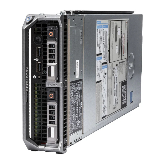
Dell PowerEdge M420 Getting Started Manual
Document
Hide thumbs
Also See for PowerEdge M420:
- Reference manual (1682 pages) ,
- Configuration manual (1246 pages) ,
- Getting started manual (202 pages)
Summary of Contents for Dell PowerEdge M420
-
Page 1: Getting Started Guide
Dell PowerEdge M1000e, M915, M910, M710HD, M710, M620, M610x, M610, M520, and M420 Getting Started Guide Regulatory Model: BMX01, DWHH, HHB, FHB, and QHB Regulatory Type: DWHH Series, HHB Series, FHB Series, and QHB Series... -
Page 2: Notes, Cautions, And Warnings
Information in this publication is subject to change without notice. © 2012 Dell Inc. All rights reserved. Reproduction of these materials in any manner whatsoever without the written permission of Dell Inc. is strictly forbidden. Trademarks used in this text: Dell... -
Page 3: Installation And Configuration
Installing A Sleeve In The Enclosure NOTE: This procedure applies only to PowerEdge M420. A sleeve includes up to four quarter-height blades to function as a system. Depending on your order, the sleeve may ship with the blades preinstalled. - Page 4 Figure 2. Installing a Sleeve NOTE: Before you install or remove a sleeve from the enclosure, ensure that the top slot of the sleeve (Blade a) is empty. You can install a blade in the top slot (Blade a) after you install the sleeve in the enclosure. Remove the orange cover from the sleeve handle.
- Page 5 Figure 4. Installing a Half-Height Blade NOTE: The above figure shows installation of a half-height blade. The procedure for installing a full-height blade is identical to installing a half-height blade. Beginning at the top, slide the blades into the enclosure from left to right. When the blade is securely installed, the blade handle returns to the closed position.
- Page 6 Connecting The System To Power Figure 6. Connecting Power to the System Connect the system’s power cables to the system power supplies. CAUTION: To prevent the power cables from being disconnected accidentally, use the plastic clip on each power supply to secure the power cable to the power supply, and use the strap to secure the power cable to the strain- relief bar.
-
Page 7: Complete The Operating System Setup
Before using your system, read the Dell Software License Agreement that came with your system. You must consider any media of Dell-installed software as BACKUP copies of the software installed on your system’s hard drive. If you do not accept the terms of the agreement, call the customer assistance telephone number. For customers in the United States, call 800-WWW-DELL (800-999-3355). -
Page 8: Obtaining Technical Assistance
NOTE: Always check for updates on support.dell.com/manuals and read the updates first because they often supersede information in other documents. Obtaining Technical Assistance Owner’s If you do not understand a procedure in this guide or if the system does not perform as expected, see your Manual . -
Page 9: Technical Specifications
Technical Specifications Owner's Manual . NOTE: For additional specifications, see your system Power — Blades Coin-cell battery 3 V CR2032 Lithium coin cell Power — Enclosure AC/DC power supply (per power supply module) Wattage 2360 W and 2700 W Connector IEC C20 Heat dissipation 1205 BTU/hr (maximum) - Page 10 Height 18.9 cm (7.4 inch) Width 5 cm (2 inch) Depth 48.6 cm (19.2 inch) Weight (maximum) 6.4 kg (14.1 lb) PowerEdge M420 Sleeve Height 39.5 cm (15.6 inch) Width 5 cm (2 inch) Depth 44.3 cm (17.4 inch) Weight 3 kg (6.61 lb)
- Page 11 Environmental NOTE: For additional information about environmental measurements for specific system configurations, see dell.com/environmental_datasheets. Temperature Operating Continuous operation: 10 °C to 35 °C at 10% to 80% relative humidity (RH), with 26 °C max dew point. De-rate maximum allowable dry bulb temperature at 1 °C/300 m above 900 m (1 °F per 550 ft).


