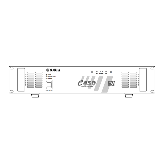
Summary of Contents for Yamaha C 160
-
Page 1: Power Amplifier
POWER AMPLIFIER Owner’s Manual Mode d’emploi Bedienungsanleitung Manual de instrucciónes TEMP PROTECTION POWER CLIP SIGNAL... - Page 2 Thank you for purchasing a Yamaha C450/320/160 series power amplifier. This series of audio amps was developed from Yamaha's wealth of experience in building PA equipment and its tradition of careful attention to every detail of circuit design. These amps feature high power and superb quality together with superior reliability and stability, guaran- teeing the highest possible audio performance.
-
Page 3: Table Of Contents
4. Do not open the case or attempt repairs or modifica- tions yourself. This product contains no user-serviceable parts. Refer all maintenance to qualified Yamaha service personnel. Opening the case and/or tampering with the internal circuitry will void the warranty. -
Page 4: Controls And Functions
Controls and Functions Front Panel TEMP PROTECTION POWER 1 POWER switch and indicator This is the main POWER switch. Press to power ON the amplifier. Press again to power OFF. The POWER indicator lights up when the amplifier is powered ON. 2 TEMP indicator When the temperature of the heat sink exceeds 85 degrees Celsius, this indicator will light red. -
Page 5: Rear Panel
Rear Panel ∞ –dB CHANNEL B CHANNEL A 1 Volume controls These volume controls allow you to adjust the volume level in 31 steps in the range between – dB and 0 dB. 2 INPUTS (CHANNEL A, B) Two types of balanced inputs for channels A and B are provided. -
Page 6: Modes: Stereo/Parallel/Bridge
Modes: STEREO/PARALLEL/BRIDGE STEREO mode In this mode, channels A and B operate independently (as a conventional stereo amp). The CHANNEL A input signal will be output from the CHANNEL A output terminals, and the CHAN- NEL B input signal will be output from the CHAN- NEL B output terminals. -
Page 7: Caution For Speaker Connection
Caution for Speaker Connection 1. Turn off the POWER switch. 2. Remove the cover attachment screw(s) and remove the protective cover from the speaker terminals. 3. After removing approx. 15 mm of insulation from the ends of the speaker cables, bind the bare ends of the speaker wires in the corresponding speaker terminals and tighten the terminals to securely clamp the wires. -
Page 8: Rack Mounting
When doing so, it is necessary for 35% or more of the entire surface area of a 1U size panel to be open. Air circulation will be even better if the top surface of the rack has ventilation openings. Ventilation panel Yamaha provides an optional 1U-size ventilation panel VP1. Mounting four or fewer amps in an open-backed rack Install the ventilation panel above the amps, as shown in the following figure. -
Page 9: Portable Rack Mounting
Portable Rack Mounting The amplifier intakes cool air through the front panel and exhausts warm air out the rear panel. When mounting amplifiers in a portable rack, make sure the rear panel is completely open for ventilation. (Side View) Front Air intake Positioning the Housed Amplifier Place the case so that the ventilation airflow paths are not blocked. -
Page 10: Specifications
Specifications General Specifications Power Output Level (Rated Power) 20 Hz~20 kHz 0.05% 1 kHz 0.05% 1 kHz, 20 ms, no clip Power Bandwidth Half Power, 0.1% Total Harmonic Distortion (THD + N) 20 Hz~20 kHz, Half Power Frequency Response Intermodulation distortion (IMD) 7 kHz: 60 Hz, 1: 4, Half Power Damping factor Input Impedance... -
Page 11: Block Diagram
Block Diagram CHANNEL A (BRIDGE) (PARALLEL) INPUT CHANNEL B Dimensions Ach Power Amp CHANNEL A PC Limiter Temperature Sensor (Heat Sink) Bch Power Amp PARALLEL BRIDGE STEREO CHANNEL B PC Limiter W:480 SIGNAL CLIP PROTECTION Protection Circuit TEMP CLIP SIGNAL Unit: mm CHANNEL A SPEAKERS... -
Page 12: Performance Graphs
Check the amplifier ventila- tion conditions and take appropriate measures to improve airflow around the amplifier. Consult your dealer or nearest Yamaha service center. C320 Output Power [W] Remedy Protection Circuit The PC limiter circuit operates to protect the power transistors.


