Table of Contents
Advertisement
Quick Links
System Enclosure
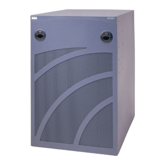
The VCO/4K system enclosure is a metal-based cabinet that houses all the VCO/4K critical system
components including: the fan cooling unit; the alarm arbiter and interface cards; and high-density
system hardware cards. It also accommodates the power subsystem, either single or dual for system
redundancy. Figure 1-1 shows the front of a VCO/4K system. Figure 1-2 shows a cutaway view of the
chassis underneath the enclosure.
The system enclosure meets or exceeds the following enclosure requirements:
UL 1950 Standard for Information Technology Equipment
•
Network Equipment-Building System (NEBS) GR-63-CORE with Zone 4 Earthquake and Bellcore's
•
GR-1089-CORE Safety and Physical Protection
General safety, including UL/CUL and EMI/EMC FCC Part 15
•
Figure 1-1
78-10334-03
The VCO/4K
C H A P T E R
Cisco VCO/4K Mechanical Assemblies
1
1-1
Advertisement
Table of Contents

Summary of Contents for Cisco VCO/4K
- Page 1 It also accommodates the power subsystem, either single or dual for system redundancy. Figure 1-1 shows the front of a VCO/4K system. Figure 1-2 shows a cutaway view of the chassis underneath the enclosure.
- Page 2 Chapter 1 System Enclosure Figure 1-2 VCO/4K Switch Enclosure and Chassis Cisco VCO/4K Mechanical Assemblies 78-10334-03...
-
Page 3: Specifications
Four screw-in rubber foot pads for bench use are provided as an option. All cable access is through the back of the system enclosure. Figure 1-3 shows the front of a VCO/4K with the door off. Figure 1-4 shows the back of the system enclosure. - Page 4 Chapter 1 System Enclosure Component Description Figure 1-3 VCO/4K (Front View—Door Off) Alarm Arbiter Card LEDs S S C C O O S S T T E E M M S S RESET AUTO SELECT ACTIVE ALARMS INSERT ONLY CARDS DESIGNATED BELOW...
-
Page 5: Front Door
Figure 1-4 VCO/4K (Rear View) Front Door The VCO/4K front door has a lock for security purposes. Two door frame latches at the top and two studs at the bottom hold the door in place. Caution The front door must remain on during system operation for NEBS EMI compliance. -
Page 6: Mounting Options
VCO/4K before it is lifted and placed in the cabinet or rack. Figure 1-5 shows the mounting brace (one on each side) for the VCO/4K. - Page 7 Mounting Brace Moving the System Enclosure If the VCO/4K is mounted in a cabinet or rack, you must remove it from the cabinet or rack before moving it to another location. Follow ESD rules when removing system components. Be sure to use a wrist strap for Caution grounding.
-
Page 8: Troubleshooting
The VCO/4K system enclosure must be installed to meet the clearance, environmental, and power criteria specified in the Cisco VCO/4K Site Preparation Guide. To reinstall the system enclosure, follow the procedures in the Cisco VCO/4K Hardware Installation Guide.


