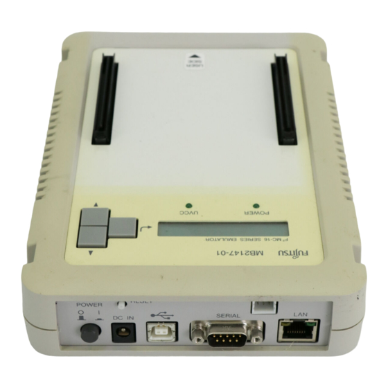
Summary of Contents for Fujitsu F2MC-16
- Page 3 This manual explains the handling of the QFP-100P Probe Header for the F MC-16L/16LX emulator. Read this manual carefully before using the MB2147-582. Consult the Sales Department or the Support Department of Fujitsu Limited for mass-produced MCUs and evaluation MCUs. *1: F MC is the abbreviation of FUJITSU Flexible Microcontroller.
- Page 4 • Any information in this document, including descriptions of function and schematic diagrams, shall not be construed as license of the use or exercise of any intellectual property right, such as patent right or copyright, or any other right of Fujitsu or any third party or does Fujitsu warrant non-infringement of any third-party' s intellectual property right or other right by using such information.
-
Page 5: Handling Precautions
1. Checking the Delivered Product Before using the QFP-100P Probe Header , confirm that the following components are included in the box: • • • • QFP-100P Probe Header • • • • Screws for securing header board (M2 × 10 mm, 0.4 mm pitch) •... - Page 6 3. Notes on Designing I Restrictions of PC board for the user system Once the header board is connected to the user system, the heights of parts mounted in the space around the header board are restricted. The PC board of the user system must be designed with due consideration given to this restriction (Figure 1).
- Page 7 I MCU footprint design notes Figure 2 shows the recommended dimensions of the NQPACK footprint mounted on the PC board of the user system. The PC board of the user system must be designed with due consideration given to this footprint as well as to the mass production MCU. For more information, contact Tokyo Eletech Corporation.
- Page 8 4. Procedure for connecting the user system I Connection Before using the QFP-100P Probe Header, mount the supplied NQPACK on the user system. To connect the header board to the adapter unit, use the flat cable (2 lines) supplied by the adapter unit sold separately.
- Page 9 Figure 4 Header board connection I Disconnection To disconnect the header board from the user system, remove all four screws, and then pull the header unit straight out of the socket.
- Page 10 5. Mounting Mass-production MCUs I Mounting After mounting a mass production MCU on the user system, use the supplied HQPACK, IC socket cover. 1. To mount a mass production MCU on the user system, match the index mark (L) on the NQPACK mounted on the user system with the index mark (G) on the mass-produced MCU.
- Page 11 SS01-71028-1E FUJITSU SEMICONDUCTOR • SUPPORT SYSTEM MC-16 FAMILY EMULATOR QFP-100P PROBE HEADER MB2147-582 OPERATION MANUAL April 2003 the first edition FUJITSU LIMITED Electronic Devices Published Edited Business Promotion Dept.


