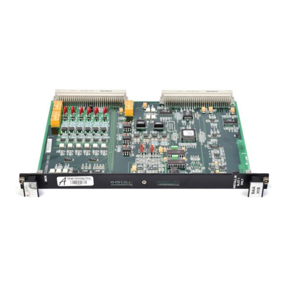
Summary of Contents for GE IS200BAIAH B Series
- Page 1 (217) 352-9330 | Click HERE Find the ABB / GE Industrial Solutions IS200BAIAH1BDC at our website:...
-
Page 2: Table Of Contents
If further information is desired or if particular problems arise that are not covered sufficiently for the purchaser’s purpose, the matter should be referred to GE Industrial Systems. -
Page 3: Application Data
The BAIA converts digital inputs from the DSPX to analog outputs: channels A and B are available for customer use at the terminal board; channels C and D are used to drive panel meters. The BAIA provides an RS-232C I/O interface between the DSPX and the drive's keypad and PC connections. -
Page 4: Testpoints And Jumpers
Testpoints and Jumpers The BAIA board provides three testpoints for signal measurement (see Figure 1). These testpoints are accessible through the top opening in the board's front panel (for factory use only). Testpoint Jumper Functions AIN1 Buffered analog input 1 AIN2 Buffered analog input 2 ICOM12... - Page 5 Table 1. Plug P2 Pin Assignments, Row A Pin No. Nomenclature Definition +5 digital power source (common) Data bus (D0) Data bus (D4) DCOM +5 digital power return (common) Data bus (D8) XD12 Data bus (D12) XD16 Data bus (D16) XD20 Data bus (D20) XD24...
- Page 6 Table 2. Plug P2 Pin Assignments, Row B Pin No. Nomenclature Definition +5 digital power source Data bus (D1) Data bus (D5) Data bus (D9) XD13 Data bus (D13) XD17 Data bus (D17) XD21 Data bus (D21) DCOM +5 digital power return (common) XD25 Data bus (D25) XD29...
- Page 7 Table 3. Plug P2 Pin Assignments, Row C Pin No. Nomenclature Definition +5 digital power source Data bus (D2) Data bus (D6) XD10 Data bus (D10) XD14 Data bus (D14) XD18 Data bus (D18) XD22 Data bus (D22) DCOM +5 digital power return (common) XD26 Data bus (D26) XD30...
- Page 8 Table 4. Plug P2 Pin Assignments, Row D Pin No. Nomenclature Definition +5 digital power source Data bus (D3) Data bus (D7) DCOM +5 digital power return (common) XD11 Data bus (D11) XD15 Data bus (D15) XD19 Data bus (D019) XD23 Data bus (D23) XD27...
- Page 9 Table 5. Plug P1 Pin Assignments, Rows A and B Pin No. Nomenclature Definition A1-A4, A6, A8, Not Connected A10, A12, A14, A16, A18, A20, A22-23, A25, A27-28 RLY1(NO) Relay 1 form C contact RLY1(COM) Relay 1 form C contact RLY1(NC) Relay 1 form C contact RLY2(NO)
- Page 10 Table 6. Plug P1 Pin Assignments, Row C Pin No. Nomenclature Definition SSR_P I24 V dc relay driver (use isolated 24 V dc & COM) C2, C4, C6, Not Connected C8, C10-16, C19, C23, C30-32 DIN1B Differential digital input 1 DIN3A Differential digital input 3 DIN4B...
- Page 11 Table 7. Plug P1 Pin Assignments, Row D Pin No. Nomenclature Definition D1, D3, D5, Not Connected D7, D9, D11, D13, D15, D31, D32 DIN1A Differential digital input 1 DIN2B Differential digital input 2 DIN4A Differential digital input 4 DIN5B Differential digital input 5 Isolated +12, −12 V dc power source COM12...
-
Page 12: Renewal/Warranty Replacement
Renewal/Warranty Replacement How to Order a Board This information helps ensure When ordering a replacement board for a GE drive, you need to know: that GE can process the order • How to accurately idenify the part accurately and as soon as possible. -
Page 13: Placing The Order
Salem, VA 24153-6492 USA Phone: +1-540-387-7595 Fax: +1-540-387-8606 Renewals (spares or those not under warranty) should be ordered by contacting the nearest GE Sales or Service Office. Be sure to include: • Complete part number and description • Drive serial number Note All digits are important when ordering or replacing any board. - Page 14 Replacement Procedures To prevent electric shock, turn off power to the board, then test to verify that no power exists in the board before touching it or any connected circuits. To prevent equipment damage, do not remove, insert, or adjust board connections while power is applied to the equipment.
- Page 15 Notes GE Industrial Systems General Electric Company Issue date: 1999-07-27 1998 by General Electric Company, USA. 1501 Roanoke Blvd. All rights reserved. Salem, VA 24153-6492 USA GEI-100268...


