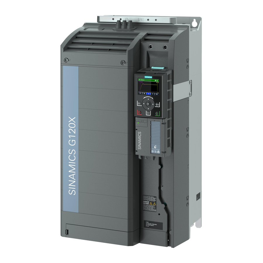
Siemens SINAMICS G120X Commissioning Manual
Permanent magnet motors pmsm
Hide thumbs
Also See for SINAMICS G120X:
- Operating instructions manual (1149 pages) ,
- Manual (39 pages)
Summary of Contents for Siemens SINAMICS G120X
- Page 1 SINAMICS G120X commissioning guide for permanent magnet motors PMSM Siemens SINAMICS G120X Industry Online https://support.industry.siemens.com/cs/ww/en/view/109780815 Support...
-
Page 2: Table Of Contents
This entry is from the Siemens Industry Online Support. The general terms of use (http://www.siemens.com/terms_of_use) apply. Security Siemens provides products and solutions with industrial security functions that support the informa- secure operation of plants, systems, machines and networks. tion In order to protect plants, systems, machines and networks against cyber threats, it is necessary to implement –... -
Page 3: Introduction
Document purpose It provides guidance for commissioning permanent magnet synchronous motors (PMSM) with SINAMICS G120X drives using the IOP-2 interface. Despite the fact the PMSM motors are not standardized and the optimal performance with G120X drive cannot be always guaranteed most party PMSM motors that meet the criteria described in this guide can be successfully commissioned. -
Page 4: Related Documents
1 Introduction Related documents SINAMICS G120X Operating instructions https://support.industry.siemens.com/cs/ww/en/view/109769350 SINAMICS IOP-2 Operating instructions https://support.industry.siemens.com/cs/ww/en/view/109767180 General system requirements for S120 drives regarding 3rd party motors (in most aspects applicable to all SINAMICS drives including G120X) https://support.industry.siemens.com/cs/ww/en/view/109760445 Support contacts Competence center in Prague gmc.tech.team.infrastructure-drive@siemens.com... -
Page 5: General Conditions Of Operation
2 General conditions of operation General conditions of operation Supported permanent magnet motor designs Supported designs: • Surface mounted permanent magnet motors SMPM (preferred) • Internal permanent magnet motors IPM • Line started permanent magnet motors LSPM (see Appendix 1 for instructions on commissioning this type of motor) Not supported designs: •... -
Page 6: General Requirements On Using
SINAMICS drives General requirements on 3rd party motors and their operations are described in the document SINAMICS S120 Requirements placed on third-party motors: https://support.industry.siemens.com/cs/ww/en/view/109760445 Most important are: • Motor insulation system – check requirements regarding voltage stress. If needed use dv/dt filter. -
Page 7: Motor Data Required For Commissioning
2 General conditions of operation Motor data required for commissioning For correct automatic setting of motor model and control loop parameters some important data must be entered into the inverter during commissioning. They can usually be found either on the motor nameplate or in the datasheet provided by the motor supplier: Table 2-1 Parameter name... -
Page 8: Operation With A Sine-Wave Filter
2 General conditions of operation Operation with a sine-wave filter Currently only G120X FSA-G support sine-wave filters. Basically a sine-wave filter with a PMSM motor can be used however the operation with long cables may lead to instability and without making a customer specific test the operation cannot be guaranteed. -
Page 9: Commissioning Using Iop-2
3 Commissioning using IOP-2 Commissioning using IOP-2 Preconditions • Mounting, wiring and safety requirements are done in accordance to G120X Operating instructions • G120X drive and IOP-2 are both in factory setting • User has fundamental skills with drive commissioning Note: If not explicitly mentioned in the following procedure the inverter setting or parameter value is to remain in factory setting. - Page 10 Dv/dt filter – just select this option to activate filter protection Sinus Filter Siemens or 3rd party – enter its inductance and capacitance values from filter nameplate or data sheet. If Siemens filter is selected the values are pre-filled already and should equal nameplate data.
- Page 11 3 Commissioning using IOP-2 Temp Sensor Select correct type of sensor if used Sometimes the motor manufacturers provide the nominal voltage of the supply grid the inverter NOTE is connected to rather than actual motor rated voltage. If the motor nameplate shows nominal mains voltage like 380V, 400V, 480V etc.
- Page 12 3 Commissioning using IOP-2 Go to Limit Settings and enter the parameters as shown in the table below. Table 3-3 Limit settings Supply Voltage If it differs from factory default value. Note that proportional derating may apply if the inverter supply voltage is lower than nominal value. Min.
- Page 13 3 Commissioning using IOP-2 If the drive is connected to fieldbus go to Fieldbus Setup and set appropriate communication parameters if necessary. Skip from the Advanced Startup menu by pressing Ok or ESC key for 2s and confirm Save Settings. Go to Parameters menu In the Parameter Filter select option Expert...
- Page 14 3 Commissioning using IOP-2 The motor cable resistance can be measured: Figure 3-1 p352 = Ω p352 = Ω /2 Always correct for measuring lead resistance (by subtracting it from the measured value) if not NOTE using precise m-Ohm meter with Kelvin leads (4-wire measurement). If measurement is not possible use calculated value based on cable length L [m], conductor cross area A [mm2] and resistivity ρ...
-
Page 15: Common Issues And Possible Solutions
3 Commissioning using IOP-2 If fault 7969 Drv: PolID incorrect appears try the remedy detailed in the Operating instruction NOTE manual in chapter: Warnings, faults and system messages. If the problem persists, try changing the PolID method in p1980. Possible values for PMSM motors are 1, 4 or 10. -
Page 16: Troubleshooting
3 Commissioning using IOP-2 3.3.2 Troubleshooting Table 3-4 Issue Possible reason Remedy Nuisance Overcurrent Due to the reasons First check the motor wiring and or Ground Fault during described in chapter 3.2 insulation resistance to confirm nuisance PolID or stationary ID Step 5, the value of tripping. -
Page 17: Appendix 1: Guidance On Commissioning Lspm - Line Started Permanent Magnet Motors
4 Appendix 1: Guidance on commissioning LSPM (Line Started Permanent Magnet motors) Appendix 1: Guidance on commissioning LSPM (Line Started Permanent Magnet motors) LSPM are special kind of PM motors comprising also the rotor cage. It allows to connect this motors D.O.L. (direct on line) similarly to asynchronous motors. Once the motor speed is close to synchronous speed the rotor magnets cause locking into synchronism and successive operation as synchronous motor.


