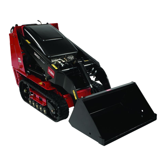
Toro TX 427 Quick Start Quide
Compact tool carrier
Hide thumbs
Also See for TX 427:
- Operator's manual (52 pages) ,
- Operation and safety manual (15 pages) ,
- Setup instructions (2 pages)
Advertisement
Quick Links
TX 427 Compact Tool Carrier
Model No. 22321—Serial No. 316000001 and Up
Model No. 22321G—Serial No. 316000001 and Up
Model No. 22322—Serial No. 316000001 and Up
Charging the Battery
WARNING
CALIFORNIA
Proposition 65 Warning
Battery posts, terminals, and related
accessories contain lead and lead compounds,
chemicals known to the State of California
to cause cancer and reproductive harm.
Wash hands after handling.
1. Open the rear access cover.
2. Connect a charger to the battery
it for a minimum of 1 hour at 6 to 10 amps. Do not
overcharge the battery.
4
2
1. Positive post
2. Negative post
WARNING
Charging the battery produces gasses that can
explode.
Never smoke near the battery and keep sparks
and flames away from battery.
3. When the battery is fully charged, unplug the charger
from the electrical outlet, then disconnect the charger
leads from the battery posts
© 2016—The Toro® Company
8111 Lyndale Avenue South
Bloomington, MN 55420
(Figure
1) and charge
3
1
G003792
Figure 1
3. Charger red (+) wire
4. Charger black (—) wire
(Figure
1).
Register at www.Toro.com.
4. Close the rear access cover.
Checking Fluid Levels
Before starting the engine for the first time, check the engine
oil and hydraulic fluid levels. Refer to the Operator's Manual
for more information.
Setting the Engine RPM (CE
Only)
If you are setting up this machine for use in the European
Community (CE), you need to permanently adjust the engine
speed so that it does not run above 3300 RPM, as follows:
1. Start the engine and run it at half throttle for 5 to 10
minutes to warm it up.
Important: The engine must be warm before
making this adjustment.
2. Move the throttle lever to the Fast position.
3. Check the engine speed on the tachometer.
It should be around 3600 RPM.
4. Loosen the jam nut securing the high idle adjusting
screw on the engine (located on the throttle/choke
control
linkage—Figure
1
2
1. High idle adjusting screw
2. Jam nut
Original Instructions (EN)
All Rights Reserved *3403-186* A
Printed in the USA
Form No. 3403-186 Rev A
2).
3
G009157
Figure 2
3. Throttle/choke control
linkage
Advertisement

Summary of Contents for Toro TX 427
- Page 1 Form No. 3403-186 Rev A TX 427 Compact Tool Carrier Model No. 22321—Serial No. 316000001 and Up Model No. 22321G—Serial No. 316000001 and Up Model No. 22322—Serial No. 316000001 and Up Charging the Battery 4. Close the rear access cover.
- Page 2 5. Turn the high idle adjusting screw outward to lower the RPM to between 3200 and 3300 RPM. Important: If you exceed 3300 RPM, the engine will not be in compliance with CE regulations and cannot be legally sold or used in the European Community.


