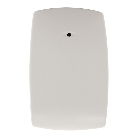
Honeywell FlexGuard 5853 Installation Instructions
Wireless glassbreak detector
Hide thumbs
Also See for FlexGuard 5853:
- Supplemental information (2 pages) ,
- Installation instructions (2 pages) ,
- Brochure & specs (41 pages)
Advertisement
Quick Links
®
FlexGuard
Refer to Supplemental Information (next page) for complete descriptions of these installation steps
5853 Glassbreak Detector Internal Parts
Latch
Mounting Hole
Front Tamper Switch
Microphone
Wall Tamper (behind battery)
Sensitivity Switches
Batteries
Test Mode pads (on PCB)
Mounting Hole
LED Indicators
Front Cover
Break out flash
for cover screw
Connect Batteries
Remove pull tab to connect batteries
Select Mounting Location
Wall Mount
(Top View)
Ceiling Mount: (Side View)
NOTE: If the device is ceiling mounted, the end with the
hole (Microphone end) should face the protected glass.
5-051-735-00C
5853 Wireless Glassbreak Detector Installation Instructions
Set Sensitivity (Range)
SENS1 & SENS2 configure sensitivity
SENSITIVITY
MAX
MEDIUM
LOW
LOWEST
NOTE: Ranges are approximate and vary with each
room's acoustic properties. Always verify range with an
ADEMCO GBS-7 or FlexGuard FG-701 Glassbreak
Simulator.
Enroll Detector
Refer to text and control panel's installation
instructions.
When programming the transmitter, specify:
•
Input Type = 3 (Supervised RF)
•
Loop Number = 1
Mount Detector
•
Use mounting holes as a template to mark
mounting locations on ceiling or wall.
•
If using the optional back tamper, remove
the batteries, then mark the wall tamper
location through its mounting hole.
•
Mount detector using appropriate hardware.
NOTE: A screw capture feature designed to
make ceiling mounting easier will cause some
resistance when inserting the screw into the
plastic.
•
Close detector cover when finished.
3.5 mm x 38 mm
(#6 x 1-1/2")
*3.5 mm (#6)
screws works best
with the screw
retention feature.
3.5 mm x 38 mm
(#6 x 1-1/2")
*The screw retention feature simplifies installation: A
rib in the screw cavity lightly holds the screw in place
when installing the detector.
Test Detector Installation
Enter Test Mode using an ADEMCO GBS-7 or
FlexGuard FG-701 Glassbreak Simulator (see Testing
the Detector on the next page). To enter Test Mode
manually, short the Test Mode pads (as shown below).
CeilingMnt-001-V0
ON
OFF
APPROXIMATE
SENS1
SENS2
RANGE
7.6m (25 ft)
OFF
OFF
4.6m (15 ft)
ON
OFF
3m (10 ft)
OFF
ON
1.5m (5 ft)
ON
ON
3.5 mm x 25 mm
(#6 x 1")
Optional Tamper Screw
TEST
TEST
Page 1
Install Cover Screw (optional)
5853_006-V1
Advertisement

Summary of Contents for Honeywell FlexGuard 5853
- Page 1 ® FlexGuard 5853 Wireless Glassbreak Detector Installation Instructions Refer to Supplemental Information (next page) for complete descriptions of these installation steps 5853 Glassbreak Detector Internal Parts Set Sensitivity (Range) Install Cover Screw (optional) Latch Mounting Hole Front Tamper Switch Microphone Wall Tamper (behind battery) Sensitivity Switches Batteries...
- Page 2 ©2002 Honeywell International Inc. All Rights Reserved Honeywell, FlexGuard and IntelliSense are registered trademarks 5-051-735-00C of Honeywell International Inc. - All other brands mentioned are the trademarks or registered trademarks of their respective owners. Specifications subject to change without prior notice.


