Advertisement
Quick Links
Download this manual
See also:
Applications Manual
Application guide
G5 flow computers
G5
µFLO
(microFLO
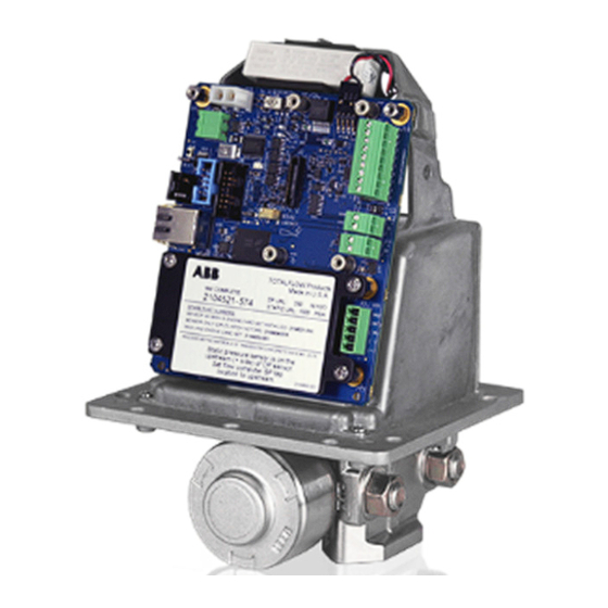
Upgrade kit
Easily upgrade to the most accurate and
reliable single run gas flow computer
Introduction
This guide is designed for typical installations only. Maintenance must be performed
by personnel knowledgeable of the ABB Totalflow
integral multivariable transducer (IMV), and the theory of natural gas electronic flow
measurement. Maintenance personnel must also be knowledgeable of local and
national codes as they apply to hazardous areas, communication wiring, and
electrical wiring.
CAUTION – Equipment damage. The µFLO
temperature range differs from the µFLO
ambient temperatures between -40 °F and +158 °F (-40 °C and +70 °C).
Do not upgrade to the µFLO
outside of this range.
Purpose
This guide provides simple instructions and information for upgrading an original
µFLO (referred to as the µFLO (G3) for clarification purposes) or a µFLO
G5
µFLO
flow computer.
G5
)
®
G5
if the ambient temperature range falls
G5
µFLO
flow computer, the
G5
flow computer operating
G4
G5
. The µFLO
is rated for
G4
to a
Advertisement

Summary of Contents for ABB G5
- Page 1 Introduction This guide is designed for typical installations only. Maintenance must be performed ® by personnel knowledgeable of the ABB Totalflow µFLO flow computer, the integral multivariable transducer (IMV), and the theory of natural gas electronic flow measurement.
-
Page 2: Additional Information
µFLO , provides additional I/O and a second communication port as a separate accessory. This board is plug and play to the new G5. Instructions for installing and wiring the optional I/O expansion board are detailed in the startup guide included with this kit. -
Page 3: Safety Warning And Note Symbols
Safety warning and note symbols Read and follow the instructions contained in this guide before and during equipment installation. Failure to do so could result in bodily injury or equipment damage. IMPORTANT NOTE: Installation and maintenance must only be conducted by personnel authorized to work on electrical installations, and in accordance with relevant national and local codes. - Page 4 In this guide, section 3.8, MMI cable replacement (G3 to G5 conversion only), beginning on page 12, is only applicable for the G3 to G5 upgrade. Please skip that section for G4 to G5 upgrades. All remaining sections are applicable to both kits.
-
Page 5: Upgrade Procedures
Upgrade procedures To upgrade the µFLO to the µFLO use the following procedures: µFLOG5 board layout label installation When upgrading to the µFLO , the upgrade kit comes with a new board layout label. This label contains information regarding the µFLO motherboard and the various pin-outs contained on the board. - Page 6 Grasp the expansion board on either side and gently lift up from the µFLO electronic board. iii. Disconnect all field wiring from the expansion board as it will need to be rewired to a G4/G5 expansion board. 6 | 2105515-001 rev. AB...
- Page 7 Prepare the IMV assembly for removal DANGER – Serious damage to health / risk to life. Preparation for removing the IMV should include shutting in the measurement sensor and disconnecting the high and low input lines or manifold connections. Depending on company policy, other steps may be required but are outside the scope of this document.
- Page 8 Remove the IMV Using a phillips screwdriver, remove the eight (8) mounting screws, washers and lock washers, located on the bottom of the enclosure, that secure the IMV to the µFLO cabinet (Figure 2). Be careful not to drop the screws. MMI connector Liquid crystal display...
- Page 9 -40 °F and +158 °F (-40 °C and +70 °C). To install the replacement G5 IMV, perform the following steps: Place the clean weather sealing gasket over the upper body of the IMV assembly and move the gasket down to the mounting plate just below the electronic board (Figure 2, µFLO IMV replacement (for illustrative purposes...
- Page 10 BOARD NUMBER NUMBER JTA G Cover p late a nd tag Figure 3: µFLO main electronic board Table 2: Onboard connections Onboard connections G3 IMV G4 IMV G5 IMV USB cable Ethernet cable LCD cable 10 | 2105515-001 rev. AB...
- Page 11 Table 4 for Digital I/O wiring information. IMPORTANT NOTES: The G3 legacy terminal connectors are not a direct swap to the G5. G4 connector terminals are a direct swap to the G5 and no rewiring is required.
- Page 12 MMI cable replacement (G3 to G5 conversion only) When upgrading from the G3 IMV to the G5 IMV, the MMI cable must be replaced. The onboard MMI cable socket is different. Use the following instructions to remove and replace the MMI cable.
- Page 13 Screw the jam nut onto the connector body outside of the enclosure and tighten. The jam nut holds the MMI connector, o-ring, and cable in place for a tight seal. Connect the MMI cable plug into J9. 2105515-001 rev. AB | 13...
- Page 14 IMPORTANT NOTES: RS-485 bus terminations are software selectable in the G5 platform. During communication setup for COMM 1, the termination must be handled through the setup screen. 14 | 2105515-001 rev. AB...
- Page 16 Should any Fax: +1 918 338 4699 discrepancies exist, the US English version will be considered final. ABB is not liable for any errors and omissions in the translated materials. Any and all derivatives of, including translations thereof, ABB Inc.


