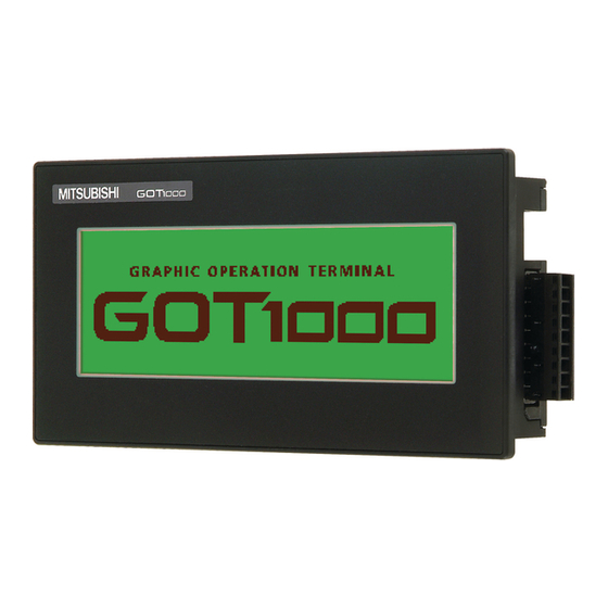
Summary of Contents for Mitsubishi Electric GT1020
- Page 1 MITSUBISHI ELECTRIC GOT1000 GT1020/GT1030 to FR-S500(E) Inverter Start-up Guide Art.-Nr.: xxxxxx INDUSTRIAL AUTOMATION 12 11 2008 MITSUBISHI ELECTRIC Version A...
- Page 3 No part of this manual may be reproduced, copied, stored in any kind of information retrieval sy- stem or distributed without the prior express written consent of MITSUBISHI ELECTRIC. MITSUBISHI ELECTRIC reserves the right to change the specifications of its products and/or the contents of this manual at any time and without prior notice.
-
Page 5: Table Of Contents
Table of Contents Table of Contents 1 Overview ............. . .1 2 Hardware Introduction . -
Page 7: Overview
GOT1000 Series touch panel interfaces used for capturing user input to a system. It should be noted that not all products from the GT1020 or GT1030 range are compatible with a FREQROL inverter connection. Compatible products are identified in the table below... -
Page 8: Cabling
Power Terminal on the back of the GOT. Communication For the GT1020/GT1030 to communicate with the inverter, a communication cable is required. The type of cable used is dependent on the number of inverters used within the system, ex- amples of which are illustrated below. -
Page 9: Got And Inverter Wiring Diagrams
Cabling Start-up Guide GOT and Inverter Wiring Diagrams GOT side Inverter side or discributor side (terminal block) (Modular connector) Cable connection and signal direction Signal Signal name Pin No. Pin layout name PU port RJ-45 plug (male) Tab. 2: RS-422 connection between inverter and GOT (Cable type A) Distributor side Inverter side or discributor side (Modular connector) -
Page 10: Got Terminals
Terminal points in detail Programming Cables The GT1020 and GT1030 come pre-installed with an OS and FX communication driver, but wi- thout any project data. To download a project from a PC running GT Designer2 to the GOT, a programming cable is required that connects to the RS-232C 6-pin Mini-DIN port on the back of the GOT. -
Page 11: Gt Designer 2
Start-up Guide GT Designer 2 (Version 2.73 or later) To make sure the GT1020/GT1030 GOT is able to use the latest functions and features, it is the responsibility of the user to check and update the firmware (Standard monitor OS) of the GOT. - Page 12 GT Designer 2 Installing OS and communication drivers To access the OS installation mode of the GT1020/GT1030, switch the GOT power from OFF to ON, while holding the bottom right corner of the touch screen (in horizontal layout), illustrated in the figure at the right.
-
Page 13: Inverter Settings
Inverter Settings Start-up Guide Inverter Settings When setting the inverter communication parameters it is important to reset the power after- wards so that the settings are saved to the inverter. The parameters shown in the following table must be set using the PU (Parameter Unit). NOTE Do not change these parameters, even though it is possible to monitor them through the GOT. -
Page 14: Indirect Specification
Start-up Guide Confirm Communication Indirect Specification When setting the station number indirectly, the station number of the inverter can be changed using the 16-bit GOT internal data register (GD10 to GD25). When specifying the station No. from 100 to 155 on GT Designer 2, the value within GD10 to GD25 is equal to the station No. Specification station no. - Page 16 Fax: +370 (0)5 / 232 2980 Fax: +380 (0)44 / 494-33-66 MITSUBISHI ELECTRIC Mitsubishi Electric Europe B.V. /// FA - European Business Group /// Gothaer Straße 8 /// D-40880 Ratingen /// Germany Tel.: +49(0)2102-4860 /// Fax: +49(0)2102-4861120 /// info@mitsubishi-automation.com /// www.mitsubishi-automation.com FACTORY AUTOMATION...


