Advertisement
FlexGuard
Refer to Supplemental Information (next page) for complete descriptions of these installation steps
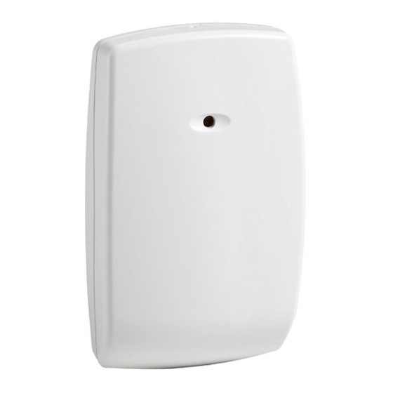
FG-1625TAS Glassbreak Detector
Mounting Hole
Microphone
With Anti-Sabotage
Wire Mesh
Terminal Block
Mounting Hole
Front Cover
Cover Screw Location
Select Mounting Location
Wall Mount
(Top View)
Ceiling Mount: (Side View)
Test Location w/ 9V Battery
V+
V
9V
9V_001-V0
Set Sensitivity & LED Configuration
SENS1 & SENS2 configure sensitivity
SENSITIVITY
APPROXIMATE
RANGE
MAX
7.6m (25 ft)
MEDIUM
4.6m (15 ft)
LOW
3m (10 ft)
LOWEST
1.5m (5 ft)
NOTE: Ranges are approximate and vary with each room's
acoustic properties. Always verify range with a FG-701
Glassbreak Simulator.
The LATCH and LED DIP switches configure LED
indicator behavior.
SWITCH
OFF
Red LED lights for 5
Red LED latches ON when
LATCH
seconds during alarm
detector goes into alarm
LED
LEDs disabled (except for
LEDs always enabled
3
power up and test mode
)
1
The timing of the alarm relay is not affected by the latched Alarm LED.
2
Reset the Alarm LED by removing/restoring power, or by toggling the
detector in and out of Test Mode.
3
LEDs can be enabled/disabled using FG-701.
5-051-741-00 Rev. B
®
FG-1625TAS Glassbreak Detector Installation Instructions
Enable Wall Tamper
•
Remove plastic tab from rear of detector.
Tamper Switch
•
Install wall tamper screw as shown.
Rear Tamper
•
Set screw depth to make contact w/ bottom of
Wire Entry Hole
tamper cavity when device is installed
Terminal Block
Test Mode Pads
LED Indicators
1625_001-V2
Connect Detector
Connect detector using 18 to 22 AWG wire, with ends
stripped approximately 6mm (1/4 in.) Use the
appropriate wiring method as shown in these diagrams:
V+
V-
NC
EOL
C
NO
Normally Closed Loop/No EOL Resistor
1625_ceiling_mnt-001-V0
V+
V-
NC
EOL
C
NO
Normally Open Loop/No EOL Resistor
SENS1
V+
SENS2
V-
LATCH
NC
LED
EOL
C
NO
SENS1
SENS2
OFF
OFF
ON
OFF
Normally Closed Loop/With EOL Resistor
OFF
ON
ON
ON
V+
V-
NC
ON
EOL
1, 2
C
NO
Normally Open Loop/With EOL Resistor
Wire Channel
Breakout Tabs
9.7 mm [.38"]
Max. screw head size
4.2 mm or 4.8 mm
[#8 or #10]
Wire Channel
Breakout Tabs
TMPR
EOL
TMPR
1625Wiring_001-V1
TMPR
EOL
TMPR
1625Wiring_002-V1
TMPR
EOL
TMPR
1625Wiring_003-V1
TMPR
EOL
TMPR
1625Wiring_004-V1
Page 1
Mount Detector
•
Place unit over wall tamper screw, if used!
•
Use mounting holes as template to mark
ceiling or wall.
•
Mount detector using appropriate hardware.
3.5 mm* or 4.2 mm
[#6 or #8]
* 3.5 mm (#6) screws
work best with the
screw retention feature.
Test Detector Installation
Enter Test Mode using FG-701 (see Testing the
Detector on the next page) or manually by shorting the
Test Mode pads (as below).
Install Cover Screw (optional)
2.9 mm (#4) screw,
6 mm (1/4-in.) long
1625_008-V1
TEST
Advertisement
Table of Contents

Summary of Contents for Honeywell FlexGuard FG-1625TAS
- Page 1 FlexGuard ® FG-1625TAS Glassbreak Detector Installation Instructions Refer to Supplemental Information (next page) for complete descriptions of these installation steps FG-1625TAS Glassbreak Detector Enable Wall Tamper Mount Detector • • Remove plastic tab from rear of detector. Place unit over wall tamper screw, if used! Tamper Switch Mounting Hole •...
- Page 2 If using optional Wall Tamper: Mark the Test Mode, event detected Flicker The user is cautioned that changes or modifications not expressly approved by Honeywell mounting location for the wall tamper screw could void the user’s authority to operate this equipment.


