Table of Contents
Advertisement
Hitachi America, Ltd.
RCU Series
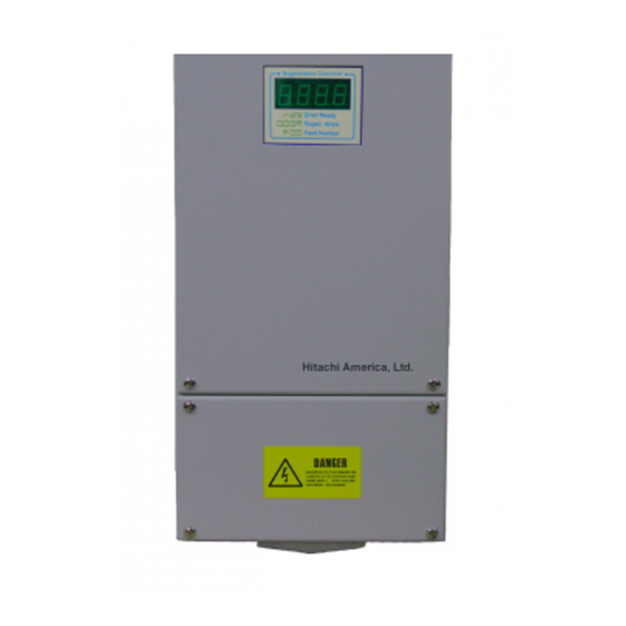
Regenerative Converter Unit
Instruction Manual
NOTE: REFER ALSO TO APPLICABLE
INVERTER INSTRUCTION MANUAL
Manual Number: HAL1057A
After reading this manual,
keep it handy for future
reference.
May 2010
Hitachi America, Ltd.
Phone: 800.894.0412 - Fax: 888.723.4773 - Web: www.clrwtr.com - Email: info@clrwtr.com
Advertisement
Table of Contents

Summary of Contents for Hitachi RCU- 2015
- Page 1 Hitachi America, Ltd. RCU Series Regenerative Converter Unit Instruction Manual NOTE: REFER ALSO TO APPLICABLE INVERTER INSTRUCTION MANUAL Manual Number: HAL1057A After reading this manual, keep it handy for future reference. May 2010 Hitachi America, Ltd. Phone: 800.894.0412 - Fax: 888.723.4773 - Web: www.clrwtr.com - Email: info@clrwtr.com...
-
Page 2: Table Of Contents
RCU Series Regenerative Converter TABLE OF CONTENTS SAFETY ..................................4 WARNINGS .................................. 4 INTRODUCTION ................................ 6 BENEFITS ..................................6 MAIN POWER CONNECTION DIAGRAM ......................6 POWER AND CONTROL CONNECTIONS ......................7 CONTROL TERMINAL FUNCTIONS ........................8 ... - Page 3 Revision History Rev A, May 2010 – Miscellaneous corrections throughout. Added cooling clearance drawing. Phone: 800.894.0412 - Fax: 888.723.4773 - Web: www.clrwtr.com - Email: info@clrwtr.com...
-
Page 4: Safety
The installer of the RCU Regenerative Converter is responsible to ensure it is installed with appropriate main switches or disconnects, and appropriate power fusing. Spare parts and service should only be obtained through Hitachi America, Ltd. Phone: 800.894.0412 - Fax: 888.723.4773 - Web: www.clrwtr.com - Email: info@clrwtr.com... - Page 5 1.2 Safety Instructions DO NOT make any connections when the Regenerative Converter is connected to the main voltage or energized inverter DC bus. DO NOT make any measurements when the Regenerative Converter is connected to the main voltage and energized inverter DC bus. After disconnecting the main power, wait until the cooling fan stops and the indicator goes out.
-
Page 6: Introduction
2. Introduction • Vertical lifting machinery or high inertia loads like elevators, cranes, centrifugal fans and centrifuges contain potential energy and inertial energy when operating. When the motor is operated by an inverter, this energy is converted back into electrical energy when the devices decelerate, lower or stop the load. -
Page 7: Power And Control Connections
5. Power and Control Connections RCU Series Shielded Phone: 800.894.0412 - Fax: 888.723.4773 - Web: www.clrwtr.com - Email: info@clrwtr.com... -
Page 8: Control Terminal Functions
Control Terminal Functions Input Signals 7: RUN When RUN input is given and DC bus voltage is higher than the RCU operating voltage, regeneration is started. 9: RCU ENABLE When RCU ENABLE input is given, RCU operation is possible. 10: EXTERNAL FAULT (A) When EXTERNAL FAULT (A) input is given, the RCU cuts output power, and regenerative converter operation is stopped. -
Page 9: Power Wiring
6. Power Wiring P : DC-Link P N : DC-Link N R(L1) , S(L2), T(L3) : 3-phase main power (Phase sequence: Automatic recognition) FG : Earth 7. Display • rdy (Ready) : Regenerative Converter is ready • 000.0: Current value during regeneration (000.0A) •... -
Page 10: Output Current And Line Voltage Waveforms
8. Output Current and Line Voltage Waveforms 9. Electrical Specifications Models 200 V Class 400 V Class Power Rating RCU-2011 RCU-4011 11 kW RCU-2015 RCU-4015 15 kW RCU-2022 RCU-4022 22 kW RCU-4030 30 kW Range 200 - 230VAC / 380VAC - 460VAC Applicable AC Power 3 Phase 200 - 230V / 380V - 460V Frequency... -
Page 11: Dimensions
10. Dimensions 11 kW and 15 kW Models Phone: 800.894.0412 - Fax: 888.723.4773 - Web: www.clrwtr.com - Email: info@clrwtr.com... - Page 12 Dimensions (cont’d) 22 kW and 30 kW Models Phone: 800.894.0412 - Fax: 888.723.4773 - Web: www.clrwtr.com - Email: info@clrwtr.com...
- Page 13 Dimension (cont’d) Be sure to observe the mounting clearances shown below to allow adequate air flow for cooling of the units. Distance(mm) *a2 is the distance between adjacent RCUs Phone: 800.894.0412 - Fax: 888.723.4773 - Web: www.clrwtr.com - Email: info@clrwtr.com...


