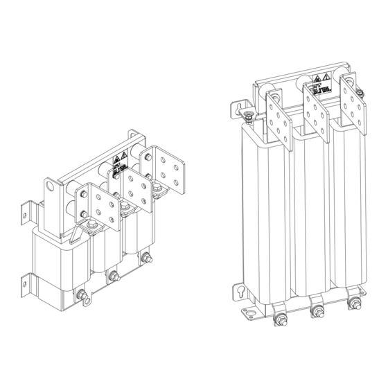
ABB ACS800 Hardware Manual
Du/dt filters; foch0320-50; foch0260-70; foch0610-70
Hide thumbs
Also See for ACS800:
- Firmware manual (340 pages) ,
- Hardware manual (210 pages) ,
- Cabinet installation and operating instruction (162 pages)
Table of Contents
Advertisement
Quick Links
Advertisement
Table of Contents

Summary of Contents for ABB ACS800
- Page 1 ACS800 Hardware Manual du/dt Filters FOCH0320-50 FOCH0260-70 FOCH0610-70...
-
Page 2: Acs800 Single Drive Manuals
ACS800 Single Drive Manuals HARDWARE MANUALS (appropriate manual is included in the delivery) ACS800-01/U1 Hardware Manual 0.55 to 200 kW (0.75 to 200 HP) 3AFE64382101 (English) ACS800-01/U1/04 Marine Supplement 0.55 to 160 kW (0.75 to 200 HP) 3AFE64291275 (English) ACS800-11/U11 Hardware Manual 5.5 to 110 kW (7.5 to 125 HP) 3AFE68367883 (English) ACS800-31/U31 Hardware Manual 5.5 to110 kW (7.5 to 125 HP) - Page 3 Filters FOCH0320-50 FOCH0260-70 FOCH0610-70 Hardware Manual 3AFE68577519 Rev C EN EFFECTIVE: 15.5.2008 © 2008 ABB Oy. All Rights Reserved.
-
Page 5: Table Of Contents
ACS800-04, ACS800-04M, ACS800-U4 ........ -
Page 6: Table Of Contents
Technical data Ambient conditions ............. .20 Dimensional drawings FOCH0260-70 . -
Page 7: About This Manual
Follow the safety instructions given in ACS800-02/U2 Hardware Manual [3AFE64567373 (English)]. ACS800-04, ACS800-04M, ACS800-U4 Follow the safety instructions given in ACS800-04 Hardware Manual 0.55 to 200 kW [3AFE68372984 (English)] or ACS800-04/04M/U4 Hardware Manual 45 to 560 kW [3AFE64671006 (English)]. About this manual... -
Page 8: Mechanical Installation And Service
Note: The installation must always be designed and made according to applicable local laws and regulations. ABB does not assume any liability whatsoever for any installation which breaches the local laws and/or other regulations. About this manual... -
Page 9: Filter Selection
(U The values in the first graph are measured with an ABB du/dt filter while the second graph without any output filtering. The values in the second graph are only representative. -
Page 10: Filter Selection
Û du/dt ------------ - (1/μs) Û du/dt ------------ - (1/μs) Cable length (m) Cable length (m) With du/dt Filter Without du/dt Filter Filter selection Step What to do See section More information Select a filter according to the drive Filter selection table The selected filter is type. -
Page 11: Filter Selection Table
Filter selection table The du/dt filter types for ACS800-01/U1, ACS800-02/U2 and ACS800-04/U4/04M drives are given below. Check that the selected filter fulfils the requirements described under section Checks. ACS800-01/U1/02/U2/04/04M/U4 type Frame size du/dt filter type 400 V 500 V 690 V... -
Page 12: Maximum Values Table
Maximum values table This table gives maximum allowed rms current (I ) and energy dissipation (E thmax values for the du/dt filters. The filter will not overheat when these values are not exceeded. Du/dt filter type * (A) (mJ) thmax FOCH0260-70 FOCH0320-50 FOCH0610-70... -
Page 13: Installation Instructions
Installation instructions What this chapter contains The chapter contains mechanical and electrical installation instructions. Planning the installation See chapter Technical data for allowed ambient conditions, maximum cable length between the drive output and the filter, maximum motor cable length and other technical data. -
Page 14: Free Space Around The Filter
Free space around the filter Free space is required around the unit for cooling as follows. The distances apply to natural convection. With forced cooling, less free space is required. 50 mm 50 mm 15 mm (1.97 in.) (1.97 in.) (0.59 in.) Space required Note: The temperature of the filter surfaces... -
Page 15: Tightening Torques
Tightening torques The following table applies to grade 8.8 screws with or without joint compound. Screw size Torque lbf ft 14.8 29.5 51.6 132.8 Mechanical installation Lift the filter by the lifting holes to the installation position. Fasten the filter with four screws at the fastening points in the mounting legs or with FOCH0320-50 and FOCH0610-70 alternatively with two screws in the upper mounting leg and four screws in the base plate of the filter core. -
Page 16: Electrical Installation
Electrical installation Drive FOCH du/dt filter Motor Grounding WARNING! The filter is grounded by the four fastening screws. Ensure that the assembly surface is in electrical connection with the factory ground and that the surface is clean and unpainted. Installation instructions... -
Page 17: Connections To Input Terminals U1. V1, W1
Connections to input terminals U1. V1, W1 The input terminals (U1, V1, W1) of the filter are made of aluminium. Use cable lugs suitable for aluminium busbars and joint grease to avoid corrosion and to ensure good electrical connection. The oxide layer must be scrubbed off from the joints before applying the grease. - Page 18 Installation instructions...
-
Page 19: Technical Data
Technical data This chapter contains the technical specifications of the du/dt filter and its installation. Input voltage (U ): 380 … 500 VAC 3-phase ± 10%, 380 … 690 VAC 3-phase ± 10%. Ratings, weights and maximum cable sizes: Filter type FOCH0320-50 FOCH0260-70 FOCH0610-70... -
Page 20: Ambient Conditions
Maximum drive output frequency: 120 Hz Maximum cable length between the drive output and the filter: 3 m Maximum motor cable length: 300 m. See also section Checks on page 11. Degree of protection: IP00 Applicable standards and markings: EN 60204-1, EN 60529, EN 61800-3, EN 50178, CE marking, UL approved insulation system, cUL approval pending. -
Page 21: Dimensional Drawings
Dimensional drawings The dimensions are given in milllimetres and [inches] below. Dimensional drawings... -
Page 22: Foch0260-70
FOCH0260-70 Dimensional drawings... -
Page 23: Foch0320-50 And Foch0610-70
FOCH0320-50 and FOCH0610-70 Dimensional drawings... - Page 24 Dimensional drawings...
- Page 26 ABB Oy ABB Inc. ABB Beijing Drive Systems Co. Ltd. AC Drives Automation Technologies No. 1, Block D, A-10 Jiuxianqiao Beilu P.O. Box 184 Drives & Motors Chaoyang District FI-00381 HELSINKI 16250 West Glendale Drive Beijing, P.R. China, 100015 FINLAND...


