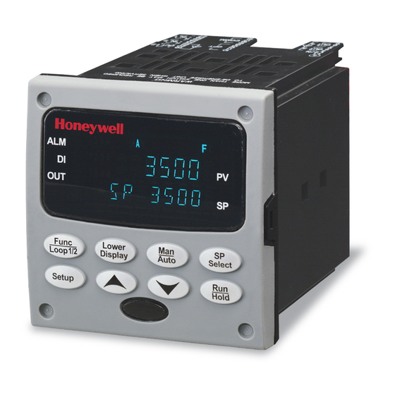
Honeywell UDC3500 Instruction
Universal digital controller
printed wiring board replacements
Hide thumbs
Also See for UDC3500:
- Product manual (460 pages) ,
- Application note (16 pages) ,
- Quick start manual (6 pages)
Advertisement
Quick Links
UDC3500 Universal Digital Controller
Printed Wiring Board Replacements
•
Kit contents
Equipment needed
Procedures
01/06
Instruction 51-52-33-153
This kit contains one of the following replacement Printed Wiring Boards:
UDC3500 MCU/Input Board – Part No. 51452828-502
•
UDC3500 Power 90-264 Vac Board – Part No. 51452831-501
•
UDC3500 Power 24 Vac/dc Board – Part No. 50006376-501
•
UDC3500 Display/Keyboard – Part No. 51452845-501
•
UDC3500 Dual Relay Board – Part No. 51452807-501
•
UDC3500 Optional Input Board – Part No. 51452825-501
•
UDC3500 Third Current Output Board – Part No. 51452834-501
•
UDC3500 Aux Out/Digital Inputs/RS-485 – Part No. 51452837-502
•
UDC3500 Digital Inputs/Ethernet Board – Part No. 51452840-501
•
UDC3500 Optional Relay Board – Part No. 51452843-501
•
• Small flat-bladed screwdriver
• Small pliers
The procedure tables that follow list the steps required to replace the old
Printed Wiring Board in your controller with the one supplied in this kit.
Kit Instruction 51-52-33-153
Continued on next page
1
Advertisement

Summary of Contents for Honeywell UDC3500
- Page 1 This kit contains one of the following replacement Printed Wiring Boards: Kit contents UDC3500 MCU/Input Board – Part No. 51452828-502 • UDC3500 Power 90-264 Vac Board – Part No. 51452831-501 • UDC3500 Power 24 Vac/dc Board – Part No. 50006376-501 •...
- Page 2 Replacement Instruction, Continued Chassis removal Table 1 How to Remove the Chassis Step Action Remove any screws in the front face. Insert a flat-bladed screwdriver into the tabs of the case as shown in Figure 1 and pry chassis forward slightly until the chassis connectors separate from the back of the case.
-
Page 3: Replacement Instruction
Replacement Instruction, Continued Printed wiring board Table 2 How to Remove the Printed Wiring Boards from the Chassis removal Step Action Remove the chassis from the case as shown in Figure 1. Separate the chassis frame at the release points shown in Figure 2 and wiggle each printed wiring board out of its socket on the display/keyboard assembly. - Page 4 Replacement Instruction, Continued Printed wiring board Figure 4 Optional Input Printed Wiring Board Identification identification Third Input Board Battery MCU / Input Board Second Input Board Printed wiring board Figure 5 Third Current Output Printed Wiring Board Identification identification Third Current Output Power / Output Board Printed wiring board Figure 6...
-
Page 5: Replacement Procedure
Replacement Instruction, Continued Replacement procedure Table 3 Board Replacement Procedure Step Action Identify the Board to be replaced from Figures 3 through 6. Replace that board with the new one. The small boards shown in Figures 4, 5 and 6 (Optional Input, Third Current Output and Dual Relay Output) are held onto the major boards with posts. - Page 6 Replacement Instruction, Continued Chassis Reassembly Figure 7 Display / Keyboard There are four slots cut in the Bezel which fit four tabs on the Display / Keyboard. Place the bottom of the Display / Keyboard into the bottom chassis slots and press the top of the display in until it snaps into place in the top chassis slots.
- Page 7 Replacement Instruction, Continued Figure 9 Communications and MCU/Input Board Chassis Reassembly Place the Communications board over the Capacitors on the Optional Input Boards. Insert these boards as an assembly into the Chassis. Start them in the chassis groves and carefully push them in until they snap into place.
- Page 8 Replacement Instruction, Continued Chassis Reassembly Figure 11 WG1 Ground Wires Plug the two ground wires onto the WG1 posts on the Power/Output Board. Wires must routed through the board notches in order to ensure that they do not interfere when the chassis is plugged into the case. Plug the Ground Wires onto the WG1 Posts...


