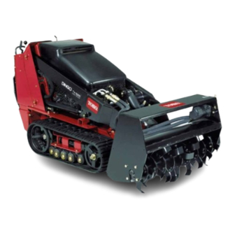
Summary of Contents for Toro 22445
- Page 1 FORM NO. 3322–129 Tiller Sitework Systems Attachment Model No. 22445 – 890001 & Up Operator’s Manual English (CE)
-
Page 2: Table Of Contents
Before adjusting, cleaning, repairing and inspecting the tiller, lower the tiller and loader arms to the ground and stop the engine. Remove the key. The Toro Company – 1999 8111 Lyndale Ave. South All Rights Reserved Bloomington, MN 55420–1196... -
Page 3: Safety Decals
WARNING WARNING POTENTIAL HAZARD POTENTIAL HAZARD There may be buried power, gas, and/or When the engine is off, attachments in the telephone lines in the area needing tilling. raised position can gradually lower. WHAT CAN HAPPEN WHAT CAN HAPPEN Shock or explosion may occur. Someone nearby may be pinned or injured by the attachment as it lowers. -
Page 4: Stability Ratings
Stability Ratings 1. Position the tiller on a level surface with enough space behind it to accommodate the traction unit. To determine the degree of slope you can traverse with the 2. Move pump control lever to slow (turtle) position. tiller installed on a traction unit, find the stability rating for the hill position you want to travel in the table below, 3. -
Page 5: Removing The Tiller From The Traction Unit
2. Move the auxiliary hydraulic lever forward, backward, 7. Start the engine, tilt the mount plate forward and back and back to neutral to relieve hydraulic pressure at the the traction unit away from the tiller. hydraulic couplers. IMPORTANT: Ensure that all foreign matter is Operation cleaned from hydraulic couplers. -
Page 6: Maintenance
Maintenance Service Interval Chart Each Storage Service Operation Hours Hours Service Notes Shaft bearing–lubricate Chain tension–adjust and lubricate initial Tines–check Replace as required Tine bolts–check and tighten Replace as required Chipped surfaces–paint CAUTION POTENTIAL HAZARD If you leave the key in the ignition switch, someone could start the engine. WHAT CAN HAPPEN Accidental starting of the engine could seriously injure you or other bystanders. -
Page 7: Tiller Tine Replacement
Tines should be installed as illustrated in Figure 5 with 2 left hand tines and 2 right hand tines on each hub. m–4414 Figure 5 1. Left hand tine 2. Right hand tine The cutting edges of the tines should face toward the rear of the tiller. -
Page 8: Troubleshooting
Troubleshooting PROBLEM POSSIBLE CAUSES CORRECTIVE ACTION Tiller does not operate. 1. Hydraulic coupler not 1. Check and tighten all couplers. completely connected 2. Defective hydraulic coupler 2. Check couplers and replace any that are defective. 3. An obstruction in a hydraulic 3.


