Advertisement
Table of Contents
SERVICE MANUAL
Ver 1.0 2004. 05
• SA-VE155 consists of the following models respectively.
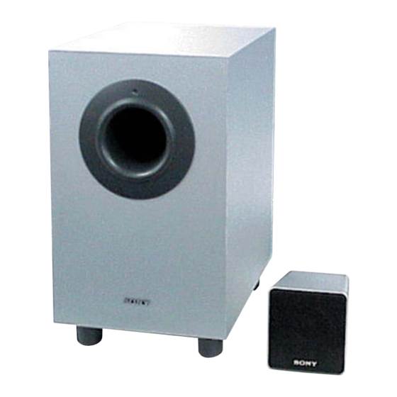
SUBWOOFER
SA-WMS155
FRONT, CENTER AND
SS-MS155
SURROUND SPEAKER
SS-MS155
(front, center and surround speakers)
Speaker system
Full range, magnetically
shielded
Speaker units
7 cm, cone type
Enclosure type
Closed type
Rated impedance
8 ohms
Power handling capacity
Maximum input power: 100 W
Sensitivity level
83 dB (1 W, 1 m)
Frequency range
120 Hz - 20,000 Hz
Dimensions (w/h/d)
Approx. 91 × 96 × 102 mm,
including front grille
Mass
Approx. 650 g each
Sony Corporation
9-877-869-01
2004E04-1
Home Audio Company
© 2004. 05
Published by Sony Engineering Corporation
SA-VE155/WMS155/
SA-WMS155
SS-MS155
SPECIFICATIONS
SA-WMS155
(subwoofer)
Speaker system
Active subwoofer,
magnetically shielded
Speaker unit
Woofer: 16 cm, cone type
Enclosure type
Bass refl ex
Reproduction frequency range
32 Hz - 200 Hz
Continuous RMS power output
55 W (4 ohms, 100 Hz,
10 % THD)
Input
LINE IN (input pin jack)
General
Power requirements
220 - 240 V AC, 50/60 Hz
Power consumptions
45 W
Dimensions (w/h/d)
E model:
Approx. 210 × 355 × 335
mm
AEP, UK model:
Approx. 210 × 355 × 330
mm
Mass
Approx. 8 kg
MICRO SATELLITE SPEAKER SYSTEM
SS-MS155
AEP Model
UK Model
E Model
Supplied accessories
Foot pads (20)
Audio connecting cord (1)
Speaker connecting cords, 10 m (2)
Speaker connecting cords, 3.5 m (3)
Design and specifi cations are subject to change
without notice.
1
Advertisement
Table of Contents

Summary of Contents for Sony SA-VE155
- Page 1 SA-VE155/WMS155/ SS-MS155 SERVICE MANUAL AEP Model UK Model Ver 1.0 2004. 05 E Model SA-WMS155 SS-MS155 • SA-VE155 consists of the following models respectively. SUBWOOFER SA-WMS155 FRONT, CENTER AND SS-MS155 SURROUND SPEAKER SPECIFICATIONS SS-MS155 SA-WMS155 Supplied accessories (front, center and surround speakers)
-
Page 2: Table Of Contents
COMPONENTS IDENTIFIED BY MARK 0 OR DOTTED LINE WITH MARK 0 ON THE SCHEMATIC DIAGRAMS AND IN THE PARTS LIST ARE CRITICAL TO SAFE OPERATION. REPLACE THESE COMPONENTS WITH SONY PARTS WHOSE PART NUMBERS APPEAR AS SHOWN IN THIS MANUAL OR IN SUPPLEMENTS PUBLISHED BY SONY. -
Page 3: General
• For details regarding the connections on the amplifi er side, : AUDIO The SA-VE155 is a 5.1 channel speaker system consisting of refer to the manual that was provided with your amplifi er. two front speakers, one center speaker, two surround speakers, and one subwoofer. -
Page 4: Printed Wiring Boards (Sa-Wms155)
SA-VE155/WMS155/SS-MS155 2-3. PRINTED WIRING BOARDS (SA-WMS155) • Refer to page 3 for Circuit Boards Location. : Uses unleaded solder. POWER SWITCH BOARD LED BOARD C810 D301 BC301 BC802 S801 1-862-218- D301 (POWER) S801 POWER TRANSFORMER BOARD POWER BOARD CN802 1-862-217-... -
Page 5: Schematic Diagram (Sa-Wms155)
SA-VE155/WMS155/SS-MS155 2-4. SCHEMATIC DIAGRAM (SA-WMS155) • Refer to page 6 for IC Block Diagram. R508 R511 IC502(2/2) R504 C507 IC501(2/2) C518 C502 C516 C517 C506 J501 R501 R503 C509 C510 R510 R506 R507 VR501 C503 IC502(1/2) R512 R509 C501 R502... -
Page 6: Ic Block Diagram
SA-VE155/WMS155/SS-MS155 2-5. IC BLOCK DIAGRAM IC601 TDA7296 (POWER Board) THERMAL BIPOLAR SHUTDOWN TRANSCONDACTANCE INPUT STAGE MOS GAIN & SHORT LEVEL SHIFTING OUTPUT CIRCUIT STAGE STAGE PROTECTION STANDBY/ MUTE BOOST- STRAP 11 12 13 14 15 SA-VE155/WMS155/SS-MS155... -
Page 7: Exploded Views
SA-VE155/WMS155/SS-MS155 SECTION 3 EXPLODED VIEWS NOTE: • The mechanical parts with no reference • Color Indication of Appearance Parts The components identified by mark 0 or dotted line with mark number in the exploded views are not supplied. Example : 0 are critical for safety. -
Page 8: Electrical Parts List
SA-VE155/WMS155/SS-MS155 SECTION 4 CONTROL ELECTRICAL PARTS LIST POWER NOTE: • Due to standardization, replacements in • Items marked “*” are not stocked since The components identified by mark 0 or dotted line with mark. the parts list may be different from the they are seldom required for routine service. - Page 9 SA-VE155/WMS155/SS-MS155 POWER POWER SWITCH TRANSFORMER Ref. No. Part No. Description Remark Ref. No. Part No. Description Remark < CONNECTOR > POWER SWITCH BOARD ******************** CN301 1-564-505-11 PLUG, CONNECTOR 2P CN601 1-564-320-00 PIN, CONNECTOR (3.96mm PITCH) 2P < CAPACITOR > 0 C810 <...
- Page 10 SA-VE155/WMS155/SS-MS155 REVISION HISTORY Clicking the version allows you to jump to the revised page. Also, clicking the version at the upper on the revised page allows you to jump to the next revised page. Ver. Date Description of Revision 2004.05...


