Table of Contents
Advertisement
Advertisement
Table of Contents

Summary of Contents for Cisco CIS2000
- Page 1 Quick Reference Guide CIS2000 IP Set-Top...
- Page 2 Notice for Installers The servicing instructions in this notice are for use by qualifi ed service personnel only. To reduce the risk of electric shock, do not perform any servicing other than that contained in the operating instructions, unless you are qualifi ed to do so. Note to System Installer For this apparatus, the coaxial cable shield/screen shall be grounded as close as practical to the point of entry of the cable...
-
Page 3: Table Of Contents
Contents IMPORTANT SAFETY INSTRUCTIONS ................2 Safety First ..........................4 Identify Your Set-Top ......................4 Front Panel Features ......................5 Back Panel Connectors ......................6 Preparation and Installation Overview ................... 7 Installation and Power On ..................... 8 Inserting Batteries into the Remote Control................9 Remote Control Features .................... -
Page 4: Important Safety Instructions
IMPORTANT SAFETY INSTRUCTIONS Read These Instructions Prevent Power Cord Damage Keep These Instructions Protect the power cord from being walked on or pinched, Heed All Warnings particularly at plugs, convenience receptacles, and the point where the cord exits from the apparatus. Follow All Instructions Power Source Warning Provide Ventilation and Select a... - Page 5 IMPORTANT SAFETY INSTRUCTIONS, continued Accessories Warning WARNING: Avoid electric shock and fi re hazard! Only use attachments/ accessories specifi ed by your service provider or the manufacturer. Service Warnings WARNING: Avoid electric shock! Do not open the cover of this product.
-
Page 6: Safety First
Safety First Before using the set-top, read the Important Safety Instructions section of this guide. Identify Your Set-Top Your service provider may ask for the serial number or the MAC address of the set-top if your system requires troubleshooting in the future. Look for the serial number and the MAC address on the bottom of the set-top. -
Page 7: Front Panel Features
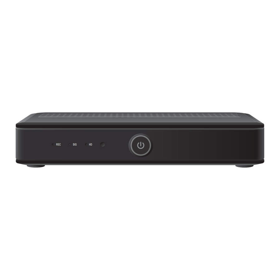
Front Panel Features Note: The CIS2000 IP set-top comes in either a black or a white chassis. The functionality and connectors are identical for either chassis. T13392 1 REC Indicates that a recording is in progress in multi-room network mode. -
Page 8: Back Panel Connectors
Back Panel Connectors Note: The CIS2000 IP set-top comes in either a black or a white chassis. The functionality and connectors are identical for either chassis. LAN 10/100 Mbits HDMI and the HDMI logo are trademarks or registered trade- marks of HDMI Licensing LLC. -
Page 9: Preparation And Installation Overview
Note: The package you receive may contain additional cables or devices. Installation and location The CIS2000 is designed for operation in closed, dry rooms with a temperature range from 5º to 40ºC. Each set-top should have at least 2 inches of open space above it and on each of its sides. -
Page 10: Installation And Power On
Installation and Power On Installation At-a-glance The following illustration shows a typical installation scenario for a CIS2000 set-top. Important: With copy-protected digital content, a reduced display quality can occur if the IP set-top is not directly connected to the TV. Therefore, connect your TV directly to the IP set-top and not through a DVD or video recorder. -
Page 11: Inserting Batteries Into The Remote Control
Inserting Batteries into the Remote Control Two batteries are needed for the remote control (Type AAA 1.5 V, included) Insert the batteries into the remote control as follows: 1. From the back of the remote control, push the tab down and pull the battery cover away from the device. -
Page 12: Remote Control Features
Remote Control Features 3 STB mode: Delete entry TV mode: Switch AV-input or switch to an external device 4 Displays the preview window 5 Volume control – Adjusts sound to be louder or quieter 6 Confi rms your selection in a menu 7 Displays the start menu 8 Returns to the last displayed page 9 Switches to TV picture... - Page 14 Licensing LLC. Other third party trademarks mentioned in this document are the property of their respective owners. The use of the word partner does note imply a partnership relationship between Cisco and any other company. (1110R) Product and service availability is subject to change without notice.


