Sign In
Upload
Manuals
Brands
Yamaha Manuals
Boat
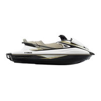
WaveRunner VXR VX1800A
Yamaha WaveRunner VXR VX1800A Manuals
Manuals and User Guides for Yamaha WaveRunner VXR VX1800A. We have
1
Yamaha WaveRunner VXR VX1800A manual available for free PDF download: Service Manual
Yamaha WaveRunner VXR VX1800A Service Manual (318 pages)
Brand:
Yamaha
| Category:
Boat
| Size: 27.98 MB
Table of Contents
Table of Contents
3
General Information
4
Safety While Working
6
Rotating Parts
6
Hot Parts
6
Electric Shock
6
Impeller
6
Handling of Gasoline
6
Ventilation
6
Self-Protection
6
Working with Crane
7
Handling of Heat Gun
7
Parts, Lubricants, and Sealants
7
Handling of Sealants
8
Special Service Tool
8
Tightening Torque
8
Non-Reusable Parts
8
Disassembly and Assembly
8
Identification Number
9
Primary I.D. Number
9
Engine Serial Number
9
Jet Pump Unit Serial Number
9
Craft Identification Number (C.I.N.) (Europe)
9
Hull Identification Number (H.I.N.) (Oceania)
9
How to Use this Manual
10
Manual Format
10
Conditions When Testing and Adjusting
11
Abbreviation
11
Adhesive, Lubricant, Sealant, and Thread Locking Agent
13
Symbols
13
Special Service Tool
14
Model Feature
24
General Feature
24
Model Equipment Comparison Table
25
Technical Tips
26
Engine Control
26
Ride System
28
Ride Motor
29
ETV System
30
Shift Control
31
Engine Control System
33
Deck and Hull
36
Lubrication System
37
Hose Routing
38
Cooling Water Flow
39
Specification
41
Model Data
42
Fuel System Technical Data
44
Fuel System
44
Power Unit
45
Power Unit Technical Data
45
Cylinder Head ASSY
45
Crankcase ASSY
46
Jet Pump Unit
48
Jet Pump Unit Technical Data
48
Electrical Technical Data
49
Ignition System
49
Charging System
49
Control System
49
Fuel System
51
Starting System
51
Meter System
52
Specified Tightening Torque
53
Torque Wrench Reading (Setting Value)
53
General Tightening Torque
53
Cable and Hose Routing
54
Starboard Bow View
54
Top View
55
Port View
57
Coupler Layout
58
Maintenance
59
Maintenance Interval Chart
60
Periodic Service
62
Fuel Line Check
62
Fuel Filler Cap and Water Separator Check
62
Fuel Tank Check
62
Water Inlet Strainer Check
62
Cooling Water Hose Check
62
Engine Oil Level Check
63
Engine Oil Replacement
63
Oil Filter Replacement
64
Intermediate Housing Lubrication
64
Spark Plug Check
64
Battery and Battery Lead Check
65
Steering Master Check
66
Steering Cable Check
66
Trim Rod Check
67
Shift Rod and Reverse Gate Check
67
Air Intake Hose Check
68
Throttle Valve Lubrication
68
Exhaust System Check
69
Breather Hose Check
69
Impeller Check
69
Jet Thrust Nozzle Check
69
Jet Vacuum Bilge Draining System Check
69
Drain Plug Check
70
Anode Check
70
Valve Clearance Measurement
70
Rubber Coupling Check
72
Engine Mount Check
72
Fuel System
73
Air Filter Case and Fuel Hose
76
Fuel Hose Disconnection
76
Fuel Pressure Measurement
76
Fuel Hose Disassembly
77
Air Filter Element Check
77
Fuel Hose Assembly
77
ETV and Fuel Injector
79
ETV Check
80
Fuel Injector Check
80
Fuel Rail and Injector Installation
80
Fuel Tank and Fuel Pump Module
82
Fuel Tank Removal
84
Fuel Pump Module Removal
85
Fuel Sender Removal
85
Fuel Pump Module Check
85
Check Valve Check
85
Fuel Filler Cap Check
86
Fuel Sender Installation
86
Fuel Pump Module Installation
86
Fuel Tank Installation
87
Power Unit
89
Power Unit
90
Engine Unit (Check and Adjustment)
92
Compression Pressure Check
92
Engine Unit
93
Exhaust Manifold
94
Engine Unit and Coupling Cover
96
Engine Mount
97
Engine Unit Removal
98
Engine Mount and Spacer Check
101
Engine Unit Installation
101
Muffler
107
Exhaust Pipe Disassembly
108
Exhaust Pipe Assembly
108
Wire Harness
109
Electrical Box
110
Starter Motor and Wire Harness Removal
112
Thermostat Check
112
Wire Harness and Starter Motor Installation
113
Intake Manifold
115
Oil Level Pipe Installation
117
Intake Manifold Installation
117
Oil Cooler, Oil Pump, and Drive Gear
118
Oil Pump and Oil Pump Drive Gear Removal
120
Oil Cooler Check
120
Oil Pump Check
120
Oil Pump Drive Gear and Oil Pump Installation
120
Cylinder Head Cover
122
Camshaft
123
Camshaft Removal
125
Camshaft Sprocket Removal
126
Camshaft Check
126
Camshaft Journal Oil Clearance Check
127
Timing Chain Tensioner Check
128
Camshaft Sprocket Installation
128
Camshaft Installation
129
Valve Clearance Adjustment
131
Valve Pad Selection Table
134
Cylinder Head
136
Valve and Valve Spring
137
Cylinder Head Disassembly
138
Cylinder Head Check
138
Valve Spring Check
138
Valve Check
139
Valve Guide Check
140
Valve Guide Removal
140
Valve Guide Installation
140
Valve Seat Check
141
Valve Seat Refacing
142
Cylinder Head Assembly
144
Cylinder Head Installation
145
Generator Cover ASSY and Flywheel Magneto
146
Generator Cover
148
Drive Coupling Removal
149
Flywheel Magneto Removal
149
Generator Cover ASSY Disassembly
151
Starter Clutch Operation Check
151
Generator Cover ASSY Assembly
152
Flywheel Magneto Assembly
153
Flywheel Magneto Installation
153
Drive Coupling Installation
156
Cylinder Block and Electrical Part
158
Oil Separator Tank and Oil Pan
160
Anode Check
162
Oil Pan Assembly
162
Oil Separator Tank Cover Installation
162
Crankcase, Connecting Rod, and Piston
164
Crankcase Disassembly
166
Connecting Rod and Piston Removal
166
Crankcase Check
166
Cylinder Block Check
167
Piston Check
167
Piston Clearance Check
167
Piston Ring Check
167
Piston Pin Check
169
Connecting Rod Check
169
Crankshaft Check
169
Crankshaft Pin Oil Clearance Check
170
Connecting Rod Big End Side Clearance Check
171
Connecting Rod Bearing Selection
172
Crankshaft Journal Oil Clearance Check
172
Crankshaft Bearing Selection
174
Connecting Rod and Piston Installation
175
Crankcase Assembly
177
Jet Pump Unit
181
Intake Grate and Ride Plate
182
Jet Pump Unit
183
Jet Pump Unit Removal
184
Impeller Check
184
Jet Pump Unit Installation
184
Trim Rod Adjustment
185
Jet Thrust Nozzle Angle Adjustment
186
Reverse Gate
188
Nozzle and Nozzle Ring
189
Impeller Housing and Impeller Duct ASSY
190
Impeller, Drive Shaft, and Impeller Duct
191
Impeller Duct ASSY Disassembly
192
Impeller Housing Check
193
Drive Shaft Check
193
Impeller Duct ASSY Assembly
193
Impeller Duct, Impeller Housing, and Nozzle Installation
195
Transom Plate and Hoses
199
Bilge Strainer Check
199
Transom Plate Installation
199
Intermediate Housing
200
Intermediate Housing Removal
201
Intermediate Housing Disassembly
201
Intermediate Housing Assembly
202
Intermediate Housing Installation
203
Electrical System
206
Electrical Components
208
Engine
208
Deck and Hull
209
Electrical Box
210
ECM Circuit Diagram
211
ECM Coupler Layout
214
Electrical Analysis
216
Electrical Component Check Using the YDIS
216
Power Supply to the ECM
216
Peak Voltage Measurement
216
Test Lead Preparation
217
Ignition System
218
Ignition Spark Check
218
Ignition Coil Check
218
Pickup Coil Check
219
Charging System
220
Stator Coil Check
220
Rectifier/Regulator Check
220
Control System
222
Oil Pressure Switch Check
222
Thermo Switch Check
222
Thermo Sensor Check
223
Engine Temperature Sensor Check
223
Intake Air Temperature Sensor Check
224
Intake Air Pressure Sensor Check
225
TPS Check
225
ETV Circuit Continuity
227
APS Check
227
APS Circuit Continuity
228
ETV Relay Check
229
RPS Check
230
RPS Circuit Continuity
230
SCU Relay Check
231
Electric Trim Switch Check
232
Cam Position Sensor Check
232
Slant Detection Switch Check
233
Steering Sensor Check
234
ECM Check
234
Earth Plate Check
235
Fuel System
236
Fuel Injector Check
236
Fuel Pump Relay Check
236
Fuel Pump Module Check
237
Starting System
238
Fuse Check
238
Handlebar Switch (Left) Check
238
Main Relay Check
238
Starter Relay Check
239
Starter Motor
241
Starter Motor Operation
242
Armature Check
242
Brush Holder Check
243
Remote Control System
244
Remote Control Transmitter Check
244
Remote Control Receiver Check
245
Transmitter Registration
245
Indication System
247
Multifunction Meter Check
247
Speed Sensor Check
247
Fuel Level Meter Display and Fuel Level Warning Indicator Check
248
Check Engine Warning Indicator Check
248
Diagnostic Display Check
249
Oil Pressure Warning Indicator Check
249
Engine Overheat Warning Indicator Check
249
Buzzer Check
250
Hull and Hood
252
Steering Pad and Handlebar Cover
254
Handlebar and Handlebar Switch
255
Lead Routing
256
Handlebar Installation
256
Front Hood
259
Side Cover
261
Center Cover
262
Steering Master ASSY
264
Steering Master
266
Steering Arm ASSY Installation
267
Steering Cable and Speed Sensor Lead
268
Steering Cable Installation (Steering Master End)
269
Steering Cable Installation (Jet Pump End)
269
Seat and Handgrip
270
Ventilation Hose and Water Separator
274
Cooling Water Pilot Outlet Installation
274
Exhaust System
275
Exhaust System Installation
277
Ride Motor
280
Ride Motor Removal
280
Ride Motor Installation
281
Ride System Initialization
283
Rear Section
284
Spout Installation
286
Reboarding Step Installation (VXR)
286
Deck and Hull
287
Troubleshooting
291
Ydis
293
Function
293
Connecting the Communication Cable to the Watercraft
295
Engine Unit Troubleshooting
296
Using the YDIS for Engine Unit Troubleshooting
296
Diagnostic Code Table
298
Diagnostic Code and Checking Step
299
Engine Unit Troubleshooting (Diagnostic Code Not Detected)
306
Appendix
313
Wiring Diagram
314
Advertisement
Advertisement
Related Products
Yamaha WaveRunner VX1800-N 2014
Yamaha WaveRunner VX1800A-N 2014
Yamaha VX110 Sport
Yamaha VX110 Deluxe WaveRunner 2006
Yamaha VX 110
Yamaha VX 1100-d
Yamaha VX 1100a-d
Yamaha VX1100A-J
Yamaha VX1100A-N
Yamaha VX1100C-N
Yamaha Categories
Motorcycle
Musical Instrument
Electronic Keyboard
Receiver
Amplifier
More Yamaha Manuals
Login
Sign In
OR
Sign in with Facebook
Sign in with Google
Upload manual
Upload from disk
Upload from URL