Sign In
Upload
Manuals
Brands
Sony Manuals
Stereo Receiver
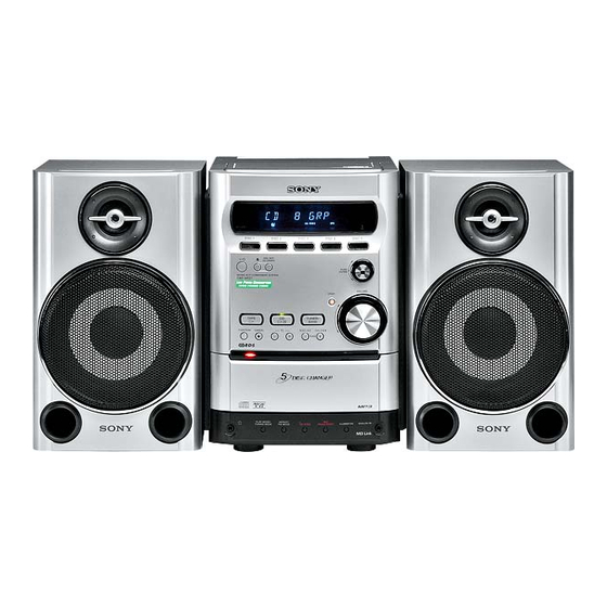
HCD-HPZ7
Sony HCD-HPZ7 Manuals
Manuals and User Guides for Sony HCD-HPZ7. We have
2
Sony HCD-HPZ7 manuals available for free PDF download: Service Manual
Sony HCD-HPZ7 Service Manual (218 pages)
MICRO HI-FI COMPONENT SYSTEM
Brand:
Sony
| Category:
Stereo Receiver
| Size: 17.05 MB
Table of Contents
Table of Contents
4
1 General
5
Setting the Clock
6
2 Disassembly
7
Disassembly Flow-1
7
Disassembly Flow-2
8
Optical Pick-Up Block
9
Side Plate (L) (R), Top Panel Section
10
Mechanical Deck
10
Front Panel Section
11
PANEL (1), (2) Board
11
Main Board
12
AMP Section
12
AMP Board
13
Rear Panel Section
13
Tuner, DC Fan
14
POWER Board
14
CD Mechanism Deck (CDM82C)
15
Plate (Cover Top)
16
Top Section
16
Arm Section
17
CD Mechanism Deck Section
18
Sub Gear (2 Step), Sub Slider Assy
19
Arm (R)
20
Gear (Stock Planet) (Right)
21
Lever (Sub Gear Back L)
21
Arm (L)
22
Gear (Stock Rot Long) (Left)
23
Gear (Stock Rot Short) (Right)
23
Stocker (1) Assy to Stocker (5) Assy
24
Lod Motor
25
Slider (Push-Popup)
25
Rotary Encoder
26
Assembling of the Rotary Encoder
27
Elv Motor
28
Chassis (Top), Chassis (Bottom)
29
Lever (Loading R, Loading L)
30
Disc Stop Lever
31
Driver Board
31
BD Board (A)
32
Optical Pick-Up (KSM-215DCP)
32
Base Unit Section
33
Lever (Bu Lock)
33
Gear (Idl-B)
34
Gear (Idl-C)
34
Spr-E (Tako-Back)
35
Plate (Push) Assy
36
Spr-P (Lock)
37
3 Assembly
38
Assembling of the Stocker Section
39
Assembling of the Gear (Stock Rot Short) (Right)
40
Assembling of the Gear (Stock Rot Long) (Left)
41
Confirming the Assembling of the Stocker Section
42
Assembling of the Gear (Stock Rotary Left)
43
Assembling of the Gear (Stock Rotary Right)
44
Assembling of the Lever (Sub Gear Back L)
45
Assembling of the Gear (Sub Gear Pin Right)
46
Assembling of the Lever (Sub Gear Back R)
47
Assembling of the Sub Gear (Idler)
48
Assembling of the Sub Gear (2 Step)
49
Confirming the Assembling of the Arm Section
50
4 Test Mode
51
5 Mechanical Adjustments
53
6 Electrical Adjustments
53
7 Diagrams
55
Block Diagram - MAIN Section
57
Block Diagram - BD/DRIVER Section
58
Block Diagram - PANEL/POWER Section
59
Printed Wiring Board - BD Board
60
Schematic Diagram - BD Board
61
Printed Wiring Board - MOTOR Section
62
Schematic Diagram - MOTOR Section
63
Printed Wiring Board - AUDIO Section
64
Schematic Diagram - AUDIO Section
65
Printed Wiring Board - MAIN Board
66
Schematic Diagram - MAIN Board
67
Printed Wiring Board - AMP Section
68
Schematic Diagram - AMP Section
69
Printed Wiring Board - PANEL (1) Board
70
Schematic Diagram - PANEL (1) Board
71
Printed Wiring Board - HEADPHONE Section
72
Schematic Diagram - HEADPHONE Section
73
Printed Wiring Board - POWER Board
74
Schematic Diagram - POWER Board
75
8 Exploded Views
84
Side Plate, Top Panel Section
84
Front Panel Section
85
Chassis Section
86
CD Mechanism Deck Section-1 (Cdm82C)
88
CD Mechanism Deck Section-2 (Cdm82C)
89
CD Mechanism Deck Section-3 (Cdm82C)
90
CD Mechanism Deck Section-4 (Cdm82C)
91
CD Mechanism Deck Section-5 (Cdm82C)
92
CD Mechanism Deck Section-6 (Cdm82C)
93
CD Mechanism Deck Section-7 (Cdm82C)
94
CD Mechanism Deck Section-8 (Cdm82C)
95
CD Mechanism Deck Section-9 (Cdm82C)
96
Base Unit Section (Bu-F1Bd83A)
97
CD Mechanism Deck Section-10 (Cdm82C)
98
9 Electrical Parts List
99
Table of Contents
112
1 Disassembly
113
Disassembly Flow-1
113
Disassembly Flow-2
114
Optical Pick-Up Block
115
Side Plate (L) (R), Top Panel Section
116
Mechanical Deck
116
Front Panel Section
117
PANEL (1) Board and PANEL (2) Board
117
MAIN Board
118
AMP Section
118
AMP Board
119
Rear Panel Section
119
Tuner, DC Fan
120
POWER Board
120
CD Mechanism Deck (CDM82C-K6BD83)
121
Plate (Cover Top)
122
Top Section
122
Arm Section
123
CD Mechanism Deck Section
124
Sub Gear (2 Step), Sub Slider Assy
125
Arm (R)
126
Gear (Stock Planet) (Right)
127
Lever (Sub Gear Back L)
127
Arm (L)
128
Gear (Stock Rot Long) (Left)
129
Gear (Stock Rot Short) (Right)
129
Stocker (1) Assy to Stocker (5) Assy
130
Loading Motor
131
Slider (Push-Popup)
131
Rotary Encoder
132
Assembling of the Rotary Encoder
133
Elv Motor
134
Chassis (Top), Chassis (Bottom)
135
Lever (Loading R, Loading L)
136
Disc Stop Lever
137
Motor Board
137
BD Board
138
Optical Pick-Up (KSM-213DCP/C2NP)
138
Base Unit Section
139
Lever (Bu Lock)
139
Gear (Idl-B)
140
Gear (Idl-C)
140
Spr-E (Tako-Back)
141
Plate (Push) Assy
142
Spr-P (Lock)
143
2 Assembly
144
Assembling of the Stocker Section
145
Assembling of the Gear (Stock Rot Short) (Right)
146
Assembling of the Gear (Stock Rot Long) (Left)
147
Confirming the Assembling of the Stocker Section
148
Assembling of the Gear (Stock Rotary Left)
149
Assembling of the Gear (Stock Rotary Right)
150
Assembling of the Lever (Sub Gear Back L)
151
Assembling of the Gear (Sub Gear Pin Right)
152
Assembling of the Lever (Sub Gear Back R)
153
Assembling of the Sub Gear (Idler)
154
Assembling of the Sub Gear (2 Step)
155
Confirming the Assembling of the Arm Section
156
3 Test Mode
157
4 Mechanical Adjustments
159
5 Electrical Adjustments
159
6 Diagrams
161
Block Diagram - BD/DRIVER Section
163
Block Diagram - MAIN Section
164
Block Diagram - PANEL/POWER Section
165
Printed Wiring Board - BD Board
166
Schematic Diagram - BD Board
167
Printed Wiring Board - MOTOR Section
168
Schematic Diagram - MOTOR Section
169
Printed Wiring Board - AUDIO Section
170
Schematic Diagram - AUDIO Section
171
Printed Wiring Board - MAIN Board
172
Schematic Diagram - MAIN Board (1/2)
173
Schematic Diagram - MAIN Board (2/2)
174
Printed Wiring Board - AMP Section
175
Schematic Diagram - AMP Section
176
Printed Wiring Board - PANEL (1) Board
177
Schematic Diagram - PANEL (1) Board
178
Printed Wiring Board - HEADPHONE Section
179
Schematic Diagram - HEADPHONE Section
180
Printed Wiring Board - POWER Board
181
Schematic Diagram - POWER Board
182
7 Exploded Views
192
Side Plate, Top Panel Section
192
Front Panel Section
193
Chassis Section
194
CD Mechanism Deck Section-1 (CDM82C-K6BD83)
195
CD Mechanism Deck Section-2 (CDM82C-K6BD83)
196
CD Mechanism Deck Section-3 (CDM82C-K6BD83)
197
CD Mechanism Deck Section-4 (CDM82C-K6BD83)
198
CD Mechanism Deck Section-5 (CDM82C-K6BD83)
199
CD Mechanism Deck Section-6 (CDM82C-K6BD83)
200
CD Mechanism Deck Section-7 (CDM82C-K6BD83)
201
CD Mechanism Deck Section-8 (CDM82C-K6BD83)
202
CD Mechanism Deck Section-9 (CDM82C-K6BD83)
203
Base Unit Section (BU-K6BD83)
204
CD Mechanism Deck Section-10 (CDM82C-K6BD83)
205
8 Electrical Parts List
206
Advertisement
Sony HCD-HPZ7 Service Manual (218 pages)
Micro Hi-Fi Component System
Brand:
Sony
| Category:
Stereo Receiver
| Size: 26.98 MB
Table of Contents
Table of Contents
4
1 General
5
Setting the Clock
6
2 Disassembly
7
Disassembly Flow-1
7
Disassembly Flow-2
8
Optical Pick-Up Block
9
Side Plate (L) (R), Top Panel Section
10
Mechanical Deck
10
Front Panel Section
11
PANEL (1), (2) Board
11
Main Board
12
AMP Section
12
AMP Board
13
Rear Panel Section
13
Tuner, DC Fan
14
POWER Board
14
CD Mechanism Deck (CDM82C)
15
Plate (Cover Top)
16
Top Section
16
Arm Section
17
CD Mechanism Deck Section
18
Sub Gear (2 Step), Sub Slider Assy
19
Arm (R)
20
Gear (Stock Planet) (Right)
21
Lever (Sub Gear Back L)
21
Arm (L)
22
Gear (Stock Rot Long) (Left)
23
Gear (Stock Rot Short) (Right)
23
Stocker (1) Assy to Stocker (5) Assy
24
Tel 13942296513
24
Lod Motor
25
Slider (Push-Popup)
25
Rotary Encoder
26
Assembling of the Rotary Encoder
27
Elv Motor
28
Chassis (Top), Chassis (Bottom)
29
Lever (Loading R, Loading L)
30
Disc Stop Lever
31
Driver Board
31
BD Board (A)
32
Optical Pick-Up (KSM-215DCP)
32
Base Unit Section
33
Lever (Bu Lock)
33
Gear (Idl-B)
34
Gear (Idl-C)
34
Spr-E (Tako-Back)
35
Plate (Push) Assy
36
Spr-P (Lock)
37
3 Assembly
38
Assembling of the Stocker Section
39
Assembling of the Gear (Stock Rot Short) (Right)
40
Assembling of the Gear (Stock Rot Long) (Left)
41
Confirming the Assembling of the Stocker Section
42
Assembling of the Gear (Stock Rotary Left)
43
Assembling of the Gear (Stock Rotary Right)
44
Assembling of the Lever (Sub Gear Back L)
45
Assembling of the Gear (Sub Gear Pin Right)
46
Assembling of the Lever (Sub Gear Back R)
47
Assembling of the Sub Gear (Idler)
48
Assembling of the Sub Gear (2 Step)
49
Confirming the Assembling of the Arm Section
50
4 Test Mode
51
5 Mechanical Adjustments
53
6 Electrical Adjustments
53
7 Diagrams
55
Block Diagram - MAIN Section
57
Block Diagram - BD/DRIVER Section
58
Block Diagram - PANEL/POWER Section
59
Printed Wiring Board - BD Board
60
Schematic Diagram - BD Board
61
Printed Wiring Board - MOTOR Section
62
Schematic Diagram - MOTOR Section
63
Printed Wiring Board - AUDIO Section
64
Schematic Diagram - AUDIO Section
65
Printed Wiring Board - MAIN Board
66
Schematic Diagram - MAIN Board
67
Printed Wiring Board - AMP Section
68
Schematic Diagram - AMP Section
69
Printed Wiring Board - PANEL (1) Board
70
Schematic Diagram - PANEL (1) Board
71
Printed Wiring Board - HEADPHONE Section
72
Schematic Diagram - HEADPHONE Section
73
Printed Wiring Board - POWER Board
74
Schematic Diagram - POWER Board
75
8 Q Q 8. Exploded Views
75
Side Plate, Top Panel Section
84
Front Panel Section
85
Chassis Section
86
CD Mechanism Deck Section-1 (Cdm82C)
88
CD Mechanism Deck Section-2 (Cdm82C)
89
CD Mechanism Deck Section-3 (Cdm82C)
90
CD Mechanism Deck Section-4 (Cdm82C)
91
CD Mechanism Deck Section-5 (Cdm82C)
92
CD Mechanism Deck Section-6 (Cdm82C)
93
CD Mechanism Deck Section-7 (Cdm82C)
94
CD Mechanism Deck Section-8 (Cdm82C)
95
CD Mechanism Deck Section-9 (Cdm82C)
96
Base Unit Section (Bu-F1Bd83A)
97
CD Mechanism Deck Section-10 (Cdm82C)
98
9 Electrical Parts List
99
Table of Contents
112
1 Disassembly
113
Disassembly Flow-1
113
Disassembly Flow-2
114
Optical Pick-Up Block
115
Side Plate (L) (R), Top Panel Section
116
Mechanical Deck
116
Front Panel Section
117
PANEL (1) Board and PANEL (2) Board
117
MAIN Board
118
AMP Section
118
AMP Board
119
Rear Panel Section
119
Tuner, DC Fan
120
POWER Board
120
CD Mechanism Deck (CDM82C-K6BD83)
121
Plate (Cover Top)
122
Top Section
122
Arm Section
123
CD Mechanism Deck Section
124
Sub Gear (2 Step), Sub Slider Assy
125
Arm (R)
126
Gear (Stock Planet) (Right)
127
Lever (Sub Gear Back L)
127
Arm (L)
128
Gear (Stock Rot Long) (Left)
129
Gear (Stock Rot Short) (Right)
129
Stocker (1) Assy to Stocker (5) Assy
130
Loading Motor
131
Slider (Push-Popup)
131
Rotary Encoder
132
Assembling of the Rotary Encoder
133
Elv Motor
134
Chassis (Top), Chassis (Bottom)
135
Lever (Loading R, Loading L)
136
Disc Stop Lever
137
Motor Board
137
BD Board
138
Optical Pick-Up (KSM-213DCP/C2NP)
138
Base Unit Section
139
Lever (Bu Lock)
139
Gear (Idl-B)
140
Gear (Idl-C)
140
Spr-E (Tako-Back)
141
Plate (Push) Assy
142
Spr-P (Lock)
143
2 Assembly
144
Assembling of the Stocker Section
145
Assembling of the Gear (Stock Rot Short) (Right)
146
Assembling of the Gear (Stock Rot Long) (Left)
147
Confirming the Assembling of the Stocker Section
148
Assembling of the Gear (Stock Rotary Left)
149
Assembling of the Gear (Stock Rotary Right)
150
Assembling of the Lever (Sub Gear Back L)
151
Assembling of the Gear (Sub Gear Pin Right)
152
Assembling of the Lever (Sub Gear Back R)
153
Assembling of the Sub Gear (Idler)
154
Assembling of the Sub Gear (2 Step)
155
Confirming the Assembling of the Arm Section
156
3 Test Mode
157
4 Mechanical Adjustments
159
5 Electrical Adjustments
159
6 Diagrams
161
Block Diagram - BD/DRIVER Section
163
Block Diagram - MAIN Section
164
Block Diagram - PANEL/POWER Section
165
Printed Wiring Board - BD Board
166
Schematic Diagram - BD Board
167
Printed Wiring Board - MOTOR Section
168
Schematic Diagram - MOTOR Section
169
Printed Wiring Board - AUDIO Section
170
Schematic Diagram - AUDIO Section
171
Printed Wiring Board - MAIN Board
172
Schematic Diagram - MAIN Board (1/2)
173
Schematic Diagram - MAIN Board (2/2)
174
Printed Wiring Board - AMP Section
175
Schematic Diagram - AMP Section
176
Printed Wiring Board - PANEL (1) Board
177
Schematic Diagram - PANEL (1) Board
178
Printed Wiring Board - HEADPHONE Section
179
Schematic Diagram - HEADPHONE Section
180
Printed Wiring Board - POWER Board
181
Q Q 6-20. Schematic Diagram - POWER Board
182
7 Exploded Views
192
Side Plate, Top Panel Section
192
Front Panel Section
193
Chassis Section
194
CD Mechanism Deck Section-1 (CDM82C-K6BD83)
195
CD Mechanism Deck Section-2 (CDM82C-K6BD83)
196
CD Mechanism Deck Section-3 (CDM82C-K6BD83)
197
CD Mechanism Deck Section-4 (CDM82C-K6BD83)
198
CD Mechanism Deck Section-5 (CDM82C-K6BD83)
199
CD Mechanism Deck Section-6 (CDM82C-K6BD83)
200
CD Mechanism Deck Section-7 (CDM82C-K6BD83)
201
CD Mechanism Deck Section-8 (CDM82C-K6BD83)
202
CD Mechanism Deck Section-9 (CDM82C-K6BD83)
203
Base Unit Section (BU-K6BD83)
204
CD Mechanism Deck Section-10 (CDM82C-K6BD83)
205
Advertisement
Related Products
Sony HCD-C900
Sony HCD-SA30
Sony HCD-GP7
Sony HCD-D115
Sony HCD-HPZ9
Sony HCD-DX400
Sony HT-1700D
Sony HT-5500D
Sony HT-1300D (CD/DVD Component)
Sony HT-17000
Sony Categories
Laptop
TV
CD Player
Camcorder
Digital Camera
More Sony Manuals
Login
Sign In
OR
Sign in with Facebook
Sign in with Google
Upload manual
Upload from disk
Upload from URL