Sign In
Upload
Manuals
Brands
Sony Manuals
Network Router
BKPF-351
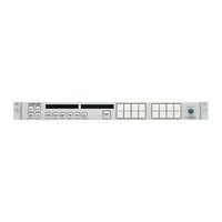
Sony BKPF-351 Manuals
Manuals and User Guides for Sony BKPF-351. We have
2
Sony BKPF-351 manuals available for free PDF download: Installation Manual, Operation Manual
Sony BKPF-351 Installation Manual (158 pages)
ROUTING SWITCHER SYSTEM
Brand:
Sony
| Category:
Network Router
| Size: 1.44 MB
Table of Contents
Table of Contents
3
Manual Structure
7
Purpose of this Manual
7
Contents
7
Related Manuals
8
DVS-128/HDS-X3000 Series and DVS-V3232M/V6464M
10
System Overview
11
Digital Routing Switcher System
11
System Control
13
Specifications and Functions of Control Port
13
S-BUS Control
15
9-Pin Remote Control
17
Connection of Control Terminal
19
Control of Monitor S-BUS System
19
Functions
21
System Settings
21
Main Functions of Router System
21
Built-In Controller
22
Matrix Sizes
22
Number of Levels
22
Number of Units
22
Protect Function
23
Secret Function
23
Crosspoint Disable Setting Function (DVS-V3232B/V6464B, BKPF-R70 and HDS-V3232)
23
Password Function (DVS-V3232B/V6464B, BKPF-R70, HDS-V3232)
23
Setting the Input/Output Name
24
(DVS-V3232B/V6464B, BKPF-R70 and HDS-V3232)
24
Virtual Mapping Function
26
(DVS-V3232B/V6464B, BKPF-R70 and HDS-V3232)
26
Free Assignment Function
27
(DVS-V3232B/V6464B, BKPF-R70 and HDS-V3232)
27
Monitor Function (BKDS-V3292B Only)
28
Tie Line Management
30
(DVS-V3232B/V6464B, BKPF-R70 and HDS-V3232)
30
Phantom Function
31
Self-Diagnosis Function
32
Route Function
33
Enhanced Restriction of Selected Block (BKS-R1607/R3210 Only)
34
Control Terminal
35
Selecting the Control Terminal
35
Control Terminal Display
36
System Status Screen
37
Menu Screen
38
Menu Screen of the Primary Station
38
Menu Screen of the Secondary Station
39
Menu Screen of the Primary Station on Monitor S-BUS
43
Menu Screen of the Secondary Station on Monitor S-BUS
43
Setting Screen
45
Setup Procedure
47
Outline
47
Preliminary Information before Installation
48
Preparation before Setup
49
Basic Setup Procedures
50
Flowchart of Setup
70
Setting up BKPF-300/301/350/351
71
System Settings
73
Setting Items of the Primary Station
73
A : Display Control Area
73
A : Display Unit Location
73
B : Set Source/Dest Type
74
C : Set Destination Name
74
D : Set Source Name
76
E : Set Level Table
78
F : Set Active Unit Number
79
G: Update Backup Controller
79
H : Set Global Phantom
80
J : Name Style
82
K : Reset to Default Table
83
K : Default Table
83
L : Set Physical Assignment
83
M: Set Inhibit Table
85
N : Set Description Name Group
86
O: Set Tie Lines
88
P : Change Password
90
Q: Change Crosspoint
90
R : Call Secondary Station
92
S : SELECT INDICATION COLOR (Except for BKPF-R70, HDS-V3232)
92
T : Set Clock
92
U : Select Remote
93
Select Warning Display
94
Confirmation of Function
95
W:system Status Log
95
Display S-Bus Communication
95
Y : DISPLAY TABLE (Except for HDS-V3232)
96
Z : Set Unit Detectable
96
Setting Items of the Secondary Station
97
A:set Unit Location
97
G:update Backup Controller
98
H : Set Phantom Table
99
K : Reset to Default Table
101
K : Default Table
101
L : Copy Table Data
101
M: SET MONITOR FUNCTION (Except for HDS-V3232)
102
N : Set Panel Table (Bks-R1601/R3202/R3203)
102
N : Set Panel Table (Bks-R1607/R1608/R3204/R3205/R3209/R3210/R1617/R1618/R3219/R3220/R1621)
103
N : Set Panel Table (Bks-R3206/R3216)
104
O: Set Available Destination (Bks-R3202/R3206)
105
O: Set Available Destination (Bks-R1607/R3210/R3216/R1617/R1618/R3219/ R3220/R1621)
105
R : Set Route (Bks-R1607/R1608/R3209/R3210/R3216/R1617/R1618/R3219/R3220/R1621)
108
S : Display Description Name
109
U : Select Remote Protocol
110
DISPLAY UNIT STATUS (Except for HDS-V3232)
111
Y : DISPLAY TABLE DATA (Except for HDS-V3232)
111
Y : Set Display Modes (Bks-R3216/R1617/R1618/R3219/R3220/R1621)
112
Z : SELECT SDI FORMAT (Except for HDS-V3232)
113
Z : Set Panel Status (Bks-R3204/R3205/R3206)
114
Z : Set Panel Status (Bks-R1607/R1608/R3209/R3210/ R3216/R1617/R1618/R3219/R3220/R1621)
115
Z : SELECT CONNECTION (DVS-RS1616 Only)
118
Z : SWITCHING FIELD (HDS-V3232 Only)
118
Setting Items of the Primary Station on Monitor S-BUS (BKDS-V3292B Only)
119
F : Set Active Unit Number
119
M: Select Monitor Function
120
R : Call Secondary Station
120
Setting Items of the Secondary Station on Monitor S-BUS (BKDS-V3293B Only)
121
M : Set Available Monitor Line (Dvs-V3232B/V6464B + Bkds-R3292B)
121
L : Copy Table Data <Monitor Menu
121
N : Set Panel Table (Bks-R1607/R1608/R3204/R3205/R3209/R3210) <Monitor Menu
122
S : Display Description Name <Monitor Menu
123
Z : Set Panel Status (Bks-R1607/R1608/R3204/R3205/R3209/R3210) <Monitor Menu
124
Backup of Setting Data
126
When Data Is Lost
126
Initialization of Table Data
127
Initializing Procedure and Corresponding Items
127
Default Values Initialization
128
Signal Switching Timing
129
Confirmation of Function
131
Outline
131
Function Check Format
132
How the Self-Diagnosis Items Are Related
133
Diagnosis Items for each Model
134
Function Check Process
135
Function Check with Control Terminal
136
System Status Screen after Power on
136
System Status Screen During the System Operation
137
Menu Item [W: SYSTEM STATUS LOG]
137
Contents and Countermeasures of the Error Messages
138
Change Information on DVS-128/HDS-X3000 Series and DVS-V3232M/V6464M
141
Outline (DVS-128/HDS-X3000 Series)
141
Changed Menu (Primary Station Setting Items)
142
Initial Screen (DVS-128/HDS-X3000 Series)
142
A : DISPLAY CONTROL AREA (DVS-128/HDS-X3000 Series)
143
B : SET SOURCE/DEST TYPE (DVS-128/HDS-X3000 Series)
143
E : SET LEVEL TABLE (DVS-128/HDS-X3000 Series)
144
O : SET TIE LINES (DVS-128/HDS-X3000 Series)
144
S : SET SOURCE ASSIGNMENT (DVS-128/HDS-X3000 Series)
146
Changed Menu (Secondary Station Setting Items)
146
N : Set Panel Table (Hds-X3400)
146
Display Unit Status (Dvs-128)
147
DISPLAY UNIT STATUS (HDS-X3000 Series)
148
Z : SET SDI FORMAT (HDS-X3000 Series)
149
Z : Select Sdi Format (Dvs-V3232M/Dvs-V6464M)
151
Appendix
155
Advertisement
Sony BKPF-351 Operation Manual (26 pages)
DIGITAL VIDEO SELECTOR BOARD, ANALOG VIDEO SELECTOR BOARD, DIGITAL AUDIO SELECTOR BOARD, ANALOG AUDIO SELECTOR BOARD
Brand:
Sony
| Category:
Computer Hardware
| Size: 0.19 MB
Table of Contents
日本語
3
Table of Contents
3
ルーティングスイッチャーシステムのマニュアル構成
6
特長と制御システム
7
S-Bus制御システムの特長
8
構成例
8
マトリックス方式による信号の切り換え
9
カスケード接続による入力の拡張
9
各部の名称と働き
10
Bkpf-300コネクターパネル
10
Bkpf-301コネクターパネル
10
Bkpf-350コネクターパネル
11
Bkpf-351コネクターパネル
11
English
16
The Routing Switcher System Manual Line-Up
17
Functions
18
Overview
18
Features and Control System of the Routing Switcher
19
Features of an S-BUS System
19
Configuration Examples
20
Expanding Inputs Using Cascade Connections
20
Signal Switching in a Matrix System
20
BKPF-300 Connector Panel
21
BKPF-301 Connector Panel
21
Location and Function of Parts
21
BKPF-350 Connector Panel
22
BKPF-351 Connector Panel
22
Specifications
23
Bkpf-300
26
Bkpf-351
26
Advertisement
Related Products
Sony BKPF-R70
Sony BKPF-R70A
Sony BKPF-300
Sony BKPF-301
Sony BKPF-350
Sony BKS-R3210
Sony BKS-R3220
Sony BKS-R3204
Sony BKS-R1617
Sony BKS-R1621
Sony Categories
Laptop
TV
CD Player
Camcorder
Digital Camera
More Sony Manuals
Login
Sign In
OR
Sign in with Facebook
Sign in with Google
Upload manual
Upload from disk
Upload from URL