Sign In
Upload
Manuals
Brands
Siemens Manuals
Control Unit
SIRIUS 3RK3
Siemens SIRIUS 3RK3 Manuals
Manuals and User Guides for Siemens SIRIUS 3RK3. We have
5
Siemens SIRIUS 3RK3 manuals available for free PDF download: Equipment Manual, System Manual, Original Operating Instructions, Operating Instruction
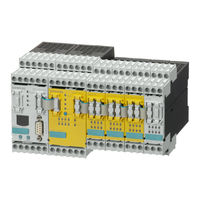
Siemens SIRIUS 3RK3 Equipment Manual (402 pages)
Modular Safety System
Brand:
Siemens
| Category:
Safety Equipment
| Size: 8.81 MB
Table of Contents
Table of Contents
3
About this Manual
11
Purpose of this Manual
11
Required Basic Knowledge
12
Validity Range
13
Topics Dealt with
14
Additional Documentation
15
Siemens Industry Online Support
16
Siemens Industry App
18
Configurator for Safety Relays
19
Evaluation of Safety Functions
20
User Responsibility for System Design and Function
21
Definitions
22
History
23
Product-Specific Information
25
General Safety Notes
25
Recycling and Disposal
27
Intended Use
28
Safety Information for Hazardous Areas
30
Current Information about Operational Safety
31
Security Information
32
Overview
33
3RK3 Modular Safety System
33
Applications
37
A Typical System Configuration of the MSS 3RK3 Main System
38
A Typical Configuration of the Subsystem with AS-Interface
39
MSS 3RK3 System Components
42
Features and Functions of the MSS 3RK3
47
Safety Systems - General Information
50
Safety Function
50
What Is Safety
51
Basic Terminology
51
Redundancy/Single-Channel and Two-Channel
51
Cross-Circuit Detection
52
Enabling Circuit
52
Solid-State Signaling Output
53
Feedback Circuit
53
Stop Categories
53
Start Function and Types
53
Two-Hand Operation/Synchronism
56
Discrepancy Monitoring
57
Sequence Monitoring
57
Startup Testing
57
Series Connection of Sensors
58
Getting Started with MSS 3RK3 Basic
61
Introduction
61
Hardware and Software Requirements
62
Task and Structure of the Example
63
Installation of the MSS 3RK3 Basic
64
Wiring of the MSS 3RK3 Basic
65
Configuration of the MSS 3RK3 Basic
68
Creating the Safety Program
69
Function Test of the MSS 3RK3 Basic
73
Description of the Hardware
75
Description of the Individual Modules
75
General Information on 3RK3 Central Units
75
Operating Elements on the 3RK3 Central Unit
75
3RK3 Basic Central Unit
76
Startup / Self-Test of the MSS 3RK3 Basic
80
3RK3 Advanced Central Unit
80
Startup / Self-Test of the MSS 3RK3 Advanced
85
3RK3 Asisafe Basic Central Unit
86
Startup/Self-Test of the MSS 3RK3 Asisafe Basic
90
3RK3 Asisafe Extended Central Unit
90
Startup/Self-Test of the MSS 3RK3 Asisafe Extended
95
General Information on Expansion Modules
96
Startup/Self-Test of the Expansion Modules
96
Expansion Module 4/8F-DI
97
Expansion Module 2/4F-DI 1/2F-RO
100
Expansion Module 2/4F-DI 2F-DO
103
Expansion Module 4F-DO
106
Expansion Module 4/8F-RO
108
Expansion Module 8DI
110
Expansion Module 8DO
112
3SK25 PROFINET Interface Module
113
3RK35 DP Interface Module
117
3SK26 Diagnostics Display
120
Mounting / Installing / Attaching
123
General Information
123
Mounting the Central Unit, Expansion Module, or DP Interface Module on a DIN Rail
125
Mounting the Central Unit, Expansion Module, or DP Interface Module on a Level Surface
125
Mounting the PROFINET Interface on a Standard Mounting Rail
126
Mounting the PROFINET Interface on a Level Surface
127
Installing the Diagnostics Display in a Control Cabinet Door / Switchboard
128
Removing the Central Unit, Expansion Module, or DP Interface Module from a Level Surface
129
Removing the Central Unit, Expansion Module, or DP Interface Module from a DIN Rail
130
Removing the Diagnostics Display
131
Disassembling the PROFINET Interface from a Level Surface
132
Disassembling Devices from a Standard Mounting Rail
132
Connecting / Wiring
134
General Information about Connection
134
Wiring Rules for Inputs and Outputs
134
Safety Information
134
Guidelines for Wiring the MSS 3RK3
136
Connecting Safety-Related Inputs
138
Connecting Non-Safety-Related Inputs
139
Connecting Safety-Related Semiconductor Outputs
140
Connecting Safety-Related Relay Outputs
141
Connecting Non-Safety-Related Outputs
143
Connecting the Central Unit, Expansion Module, or DP Interface
144
Connection Data for Terminal Blocks
144
Connecting Terminal Blocks
145
Connect the Interfaces (X1, X2)
147
Connecting a Diagnostics Display
150
Establishing a PROFIBUS DP Connection
151
Connecting the AS-I Bus
153
Disconnecting
154
Plugging in Terminal Blocks
156
Inserting and Sealing the Memory Module
157
Grounding
158
Connect 3SK25 PROFINET Interface
159
General Information about Connection
159
Terminal Assignment
160
Terminal Coding
161
Connecting the Screw-Type Terminals
162
Disconnecting the Screw-Type Terminals
162
Connecting the Push-In Terminals
163
Disconnecting the Push-In Terminals
165
Attaching the Terminals
166
Removing the Terminals
167
Establishing a 3SK25 PROFINET Interface Connection
168
Disassembly of the PROFINET Connector
170
Operation
171
Response Times
171
Notes and Definitions
171
Reaction Time of the Logic (in Error-Free Operation)
172
Fault Reaction Time of the Logic (Single-Channel Actuator Circuit)
173
Fault Reaction Time of the Logic (Two-Channel Actuator Circuit)
173
Reaction Times "Sensor - Actuator
174
Examples of the Total Response Time with MSS 3RK3 Advanced
178
Parameterizing in Safety es
185
Selection of Sensors and Actuators
188
Requirements for Sensors
188
Minimum Actuating Duration at the Inputs
188
Requirements for Actuators
188
Dark Test
189
Guidelines for Capacitive Loads
190
Guidelines for Inductive Loads
190
Commissioning
192
Modes
192
Integrating into DP Master Systems
194
DP Address of the DP Interface
194
Configuring in STEP 7 with GSD File
195
Failure and Restoration in the Case of PROFIBUS
196
Operating the 3RK35 DP Interface
197
Operator Controls and Display Elements on the DP Interface
197
Standard Mode with Status Display
198
Menu of the DP Interface
199
Setting the PROFIBUS Address
199
Restoring Factory Settings
201
Connecting to the AS-I Master Via AS-Interface
202
3RK3 Central Unit with AS-I Interface
202
Communication of MSS 3RK3 with AS-I Interface
203
Asisafe
204
Addressing and Configuring AS-I Components in Safety es
205
Overview of Possible Incoming and Outgoing AS-I Signals
206
Teaching the Code Sequences
208
Code Sequences
208
Teaching Code Sequences
208
Canceling Teaching of Code Sequences
211
Missing / Incorrect Code Sequences
211
Functions of the MSS 3RK3 on the AS-I Bus
214
Safety-Related Data Exchange, for Example, in Multiple Subnetworks
215
Simulated AS-I Slaves
216
Simulation of Non-Safety-Related AS-I Slaves
217
Simulation of Safety-Related AS-I Input Slaves
219
Control of Safety-Related AS-I Outputs
220
Representation of Safety-Related AS-I Outputs
224
MSS 3RK3 Advanced as the Safety Monitor
226
Monitoring of Non-Safety-Related AS-I Slaves
227
Monitoring of Safety-Related AS-I Input Slaves
229
Behavior on Failure of AS-I Components
232
Acknowledgement Behavior
232
Failure of an AS-I Slave
233
Failure of the AS-I Bus
233
Integration into PROFINET Master Systems
235
Setting the PROFINET Communication Parameters
235
Options
235
Setting and Transferring Device Names
236
Setting and Transferring the IP Parameters
238
Configuring in STEP 7 with GSD File
240
Failure and Restoration in the Case of PROFINET
241
Operating the 3SK25 PROFINET Interface
243
Displays on the 3SK25 PROFINET Interface
243
Defining PROFINET Communication Parameters
243
Restoring Factory Settings
244
Diagnostics / Service
245
Troubleshooting Procedure
246
Diagnostics Concept
247
Display Philosphy
248
Error Management
248
Diagnostics with Leds
253
SF" on the Expansion Module Lights up Red
256
Leds on the Modules
257
Displays on the 3RK3 Basic Central Unit
257
Displays on the 3RK3 Advanced Central Unit
259
Displays on the 3RK3 Asisafe Basic Central Unit
260
Displays on the 3RK3 Asisafe Extended Central Unit
262
Displays on the Expansion Module 4/8F-DI
264
Displays on Expansion Module 2/4F-DI 1/2F-RO
265
Displays on Expansion Module 2/4F-DI 2F-DO
266
Displays on Expansion Module 4F-DO
266
Displays on Expansion Module 4/8F-RO
267
Displays on Expansion Module 8DI
267
Displays on Expansion Module 8DO
267
Displays on the PROFINET Interface
268
Displays on the DP Interface
269
Displays on Diagnostic Display
269
LED Response for Various Element Functions
270
Monitoring Universal
270
Emergency Stop
271
Espe
272
Protective Door
273
Protective Door with Lock
274
Safety Shutdown Mat with NC Principle
276
Safety Shutdown Mat with Cross-Circuit Principle
277
Two-Hand Operation
278
Enabling Button
279
Mode Selector Switch
279
Muting Functions
280
Output Functions
281
Messages for AS-I 1
282
Diagnostics Via PROFINET
283
Using Data Sets
283
Description of the Diagnostic Data Sets
285
Diagnostics Using PROFIBUS
288
Using Data Sets
288
Structure of the Diagnostics Frame
290
Data Set 0
294
General Data Set 0
294
Data Set 0 in 3RK3 Central Unit
294
Data Set 0 in DP Interface
295
Data Set 1
295
Data Set 1 in the 3RK3 Central Unit
295
Data Set 1 in DP Interface
297
Diagnosis Using AS-Interface (CTT2 Protocol)
298
Diagnostics Concept Using the CTT2 Protocol
298
Diagnostics Using the CTT2 Protocol
298
Cyclic Data
300
Acyclic Data Transmission with Function Block
302
CTT2 Data Exchange
303
Structure of the Transfer Protocol
308
Error Codes "CTT2 Error Code
309
Diagnostics Using the CTT2 Protocol
310
Reading / Writing Data Set 3
310
Structure of the Element Data Blocks
311
Element Messages
312
Element Status
326
Diagnostics with Diagnostics Display
328
Diagnostics Display
328
Displays
329
Operator Controls and Displays on the Diagnostics Display
330
Menus
332
Messages
334
Status
338
System Configuration
341
Display Settings
344
Restoring Factory Settings
347
Module Replacement
349
Replacement of AS-I Components
351
Replacement of an AS-I Slave During Running Operation
351
Replacing an AS-I Slave in Different Subnetworks
353
Replacement of Multiple AS-I Slaves During Running Operation
354
Additional AS-I Slave in Running Operation
355
Replacement of MSS 3RK3 with AS-I Interface
355
Description of the Diagnostic Data Sets
357
Data Set 92
357
Technical Data
365
Technical Data in Siemens Industry Online Support
365
General Technical Data
366
3RK3 Basic Central Unit
367
3RK3 Advanced Central Unit
369
3RK3 Asisafe Basic Central Unit
371
3RK3 Asisafe Extended Central Unit
373
Em 4/8F-DI
375
Em 2/4F-DI 1/2F-Ro
376
Em 2/4F-DI 2F-Do
378
Em 4F-Do
379
Em 4/8F-Ro
380
Em 8Di
381
Em 8Do
382
PROFINET Interface Module
383
DP Interface Module
384
Diagnostics Display
385
Memory Module
386
Dimension Drawings
387
Diagnostics Display
393
PROFINET Interface
394
DP Interface
395
Index
397
Advertisement
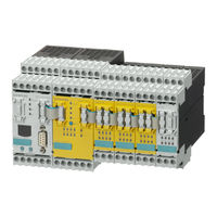
Siemens SIRIUS 3RK3 System Manual (318 pages)
Modular Safety System Industrial Switchgear Monitoring and Control Devices
Brand:
Siemens
| Category:
Security Sensors
| Size: 13.34 MB
Table of Contents
Table of Contents
5
1 About this Manual
13
Purpose of this Manual
13
Required Basic Knowledge
13
Topics Dealt with
13
Validity Range
14
Additional Documentation
14
Definitions
14
Correction Sheet
14
User Responsibility for System Design and Function
15
2 Product-Specific Information
17
General Safety Notes
17
Safety Information for Hazardous Areas
18
Guidelines for Inductive Loads
18
Intended Use
20
Current Information about Operational Safety
21
3 Overview
23
Introduction
23
A Typical System Configuration
24
System Components
25
4 Getting Started
29
Introduction
29
Hardware and Software Requirements
29
Task and Structure of the Example
30
Installing the MSS
32
Wiring the MSS
33
Configuring the MSS
36
Creating the Safety Program
38
MSS Function Test
41
5 Description of the Hardware
43
Description of the Individual Modules
43
General Information on Central Units
43
3RK3 Basic Central Unit
44
General Information on Expansion Modules
47
Expansion Module 4/8F-DI
47
Expansion Module 2/4F-DI 1/2F-RO
49
Expansion Module 2/4F-DI 2F-DO
51
Expansion Module 4F-DO
53
Expansion Module 4/8F-RO
55
Expansion Module 8DI
57
Expansion Module 8DO
58
DP Interface Module
60
Diagnostics Module
63
Mounting/Installing/Attaching
66
Mounting the Central Unit, Expansion Module, or Interface Module on a DIN Rail
66
Mounting the Central Unit, Expansion Module, or Interface Module on a Level Surface
66
Installing the Diagnostics Module in a Control Cabinet Door/Switchboard
67
Removing the Central Unit, Expansion Module, or Interface Module
68
Removing the Diagnostics Module
70
Connecting/Wiring
71
Connecting Safety-Related Inputs and Outputs
71
Connecting Non-Safety-Related Inputs and Outputs
74
Guidelines for Wiring the MSS
74
Connection Data for Terminal Blocks
76
Connecting Terminal Blocks
76
Connecting the System Interfaces
78
Connecting a Diagnostics Module
79
Establishing a PROFIBUS DP Connection
81
Disconnecting
82
Plugging in Terminal Blocks
85
Connecting the Memory Module
86
Grounding
87
6 Description of the Software
89
Introduction
89
Overview
89
License-Dependant Available Menu Commands
90
Requirements
93
Installation and Program Start
94
Automation License Manager
94
Usage Authorizations Via the Automation License Manager
94
Installing the Automation License Manager
95
Rules for Using License Keys
96
Installation
96
Starting the Program
97
User Interface
98
Design of the User Interface
98
Toolbar
99
Status Bar
100
Description of the Menu Commands
101
Switching Device Menu
101
New
101
Open
101
Import
101
Open Online
102
Save
102
Save as
102
Export
103
Close
103
Information about the Print Options
103
Page Setup
104
Print Preview
106
Print
106
List of the Files Last Used
107
Exit
107
Edit Menu
108
Undo
108
Redo
108
Cut
108
Copy
108
Paste
108
Delete
108
Select All
108
Go to
109
Insert Comment
109
Realign Graphic
109
Interrupt Connection
109
Redraw Partial Connection
110
Add Diagram
110
Remove Diagram
110
Edit Terminal Identifier
110
Object Properties
111
Check Consistency
111
Password for Project Access
111
Forgot Password
111
Reset Password for Project Access
112
Password for Device Access
112
Password for Test Mode
113
Compare with File
113
Compare with Switching Device
113
Target System Menu
114
Load to Switching Device
114
Load to PC
114
Go Offline
114
Prepare Configuration Test
115
Approve Configuration
116
Cancel Configuration Release
116
Configuring Mode
117
Test Mode
117
Safety Mode
117
Commands
118
Diagnostics Configuration
119
Diagnostics Logic
119
View Menu
120
Zoom in
120
Zoom out
121
Zoom Dialog
121
Overall View
121
Highlight Signal Flow
121
Delete Highlighting
121
Navigation Window
121
Output Window
121
Catalog Window
121
Minimize / Restore Online Dialogs
121
Options Menu
122
Basic Settings
122
Modular Safety System es Settings - "General" Tab
123
Settings of Modular Safety System es - "Download Settings" Tab
123
Settings of Modular Safety System es - "Logic" Tab
124
Cross References
124
Symbol List
124
Release Information
125
Set PG/PC Interface
125
Help Menu
125
Help Topics
125
Info
126
Identification and Configuration
127
Identification
127
Central Unit
127
Marking
128
Project
129
Messages During the Consistency Check - Identification
129
Configuration
131
Main System
131
Swap Slots
133
Central Unit Properties
133
Properties of Interface Modules
134
Properties of Expansion Modules
135
Messages During the Consistency Check - Configuration
136
Logic Diagram
137
Overview
137
Features of the Logic Diagram
138
Symbols of the Toolbar in the Logic Diagram
140
Working with the Logic Diagram
141
Selecting Functions and Using Them in the Diagram
141
Connecting Functions
141
Selecting
144
Delete
144
Display of Graphical Conflicts
144
Realign Graphic
145
Move the Diagram
147
Zoom Dialog
147
Overall View
150
Inserting a Comment
150
Interrupt Connection
151
Redraw Partial Connection
153
Highlight Signal Flow
154
Delete Highlighting
155
Display Settings
155
Grids and Lines
157
Errors and System Callbacks
158
Connection Rules
158
Messages During the Consistency Check - Logic
160
Functions
162
Fixed-Value Parameters
162
Cell Functions
165
Input Cell
165
Output Cell
166
Monitoring Functions
167
Emergency Stop
167
ESPE (Electro-Sensitive Protective Equipment)
169
Safety Shutdown Mat (NC Principle)
171
Safety Shutdown Mat (Cross-Circuit Principle)
172
Protective Door
174
Enabling Button
176
Two-Hand Operation
177
Mode Selector Switch
179
Status Functions
181
Device Status
181
Control Functions
182
Device Command
182
Logic Functions
183
And
183
Xor
185
Nand
186
Nor
187
Negation (Neg)
188
Flip-Flop
189
Ff-Sr
189
Counter Functions
190
Counter (0 -> 1)
190
Counter (1 -> 0)
191
Counter (0 -> 1 / 1 -> 0)
193
Timer Functions
195
With on Delay
195
With on Delay (Trigger)
196
Passing Make Contact
197
Passing Make Contact (Trigger)
199
With off Delay
200
With off Delay (Trigger)
201
Clocking
203
Start Functions
204
Monitored Start
204
Manual Start
205
Output Functions
206
Standard Output
206
F Output
207
7 Operator Control
209
Response Times
209
Passwords
212
Planning/Configuring
215
Modes
215
Commissioning
216
Testing the Configuration
218
Forcing
219
Configuration Release
221
Safety Mode
222
Operation with MSS es
224
Comparison Function
224
Cross References
225
Symbol List
226
Integrating the Modular Safety System 3RK3 in DP Master Systems
227
Setting and Changing the DP Address
227
DP Interface
228
DP Interface Menu Navigation
229
Menu Mode with User Control
229
Configuration in STEP 7 HW Config
233
Failure and Restoration in the Case of PROFIBUS
235
8 Diagnostics / Service
237
Error Management
237
Diagnostics Via Leds
240
Displays on the 3RK3 Basic
240
Displays on the EM 4/8F-DI
241
Displays on the EM 2/4F-DI 1/2F-RO
241
Displays on the EM 2/4 F-DI 2 F-DO
242
Displays on the EM 4F-DO
242
Displays on the 4/8F-RO
242
Displays on the EM 8DI
243
Displays on the EM 8 DO
243
Displays on the DP Interface
243
Displays on the Diagnostics Module
244
Diagnostics with Diagnostics Module
245
Diagnostics Module
245
Displays
246
Operator Controls and Displays
247
Menus
248
Messages
249
Status
251
System Configuration
253
Display Settings
255
Diagnostics with MSS es
258
Diagnostics Configuration
258
Module Status
258
Dialog "Device Messages" > "Overview" Tab
259
Dialog "Device Messages" > "Configuring" Tab
260
Dialog "Device Messages" > "Hardware" Tab
261
Dialog "Device Messages" > "PROFIBUS DP" Tab
262
Dialog "Device Messages" > "Device Bus Interface" Tab
262
Diagnostics Logic
263
Monitoring
263
Element Messages
264
Diagnostics with Data Sets
272
Using Data Sets
272
Structure of the Diagnostics Frame
274
Data Set 0
276
General Data Set 0
276
Data Set 0 in MSS Central Unit
276
Data Set 0 in DP Interface
277
Data Set 1
278
Data Set 1 in the MSS Central Unit
278
Data Set 1 in DP Interface
279
Data Set 92
280
Restoring Factory Settings
286
Module Replacement
288
9 Technical Data
291
General Technical Data
291
Central Unit
292
Em 4/8F-DI
293
Em 2/4F-DI 1/2F-Ro
294
Em 2/4F-DI 2F-Do
295
Em 4F-Do
296
Em 4/8F-Ro
297
Em 8Di
298
Em 8Do
299
MSS DP Interface Module
300
Diagnostics Module
300
Memory Module
301
Dimension Drawings
303
A.1 Dimension Drawings
303
Evaluation/Feedback
309
Certificates
311
C.1 Certificates
311
Index
313
Siemens SIRIUS 3RK3 Original Operating Instructions (21 pages)
MSS expansion modules
Brand:
Siemens
| Category:
Control Unit
| Size: 2.76 MB
Advertisement
Siemens SIRIUS 3RK3 Original Operating Instructions (19 pages)
MSS central modules
Brand:
Siemens
| Category:
Control Unit
| Size: 3.26 MB
Siemens SIRIUS 3RK3 Operating Instruction (3 pages)
Diagnostics display
Brand:
Siemens
| Category:
Monitor
| Size: 1.15 MB
Advertisement
Related Products
Siemens 3RK3122
Siemens 3RK3111
Siemens 3RK3131
Siemens 3RK3121
Siemens SIRIUS 3RK3221
Siemens SIRIUS 3RK3241
Siemens SIRIUS 3RK3251
Siemens SIRIUS 3RK33311
Siemens SIRIUS 3RK3211
Siemens SIRIUS 3RK3242
Siemens Categories
Industrial Equipment
Controller
Control Unit
Oven
Washer
More Siemens Manuals
Login
Sign In
OR
Sign in with Facebook
Sign in with Google
Upload manual
Upload from disk
Upload from URL