Sign In
Upload
Manuals
Brands
Siemens Manuals
Media Converter
6SN1123-1AB00-0CA1
Siemens 6SN1123-1AB00-0CA1 Manuals
Manuals and User Guides for Siemens 6SN1123-1AB00-0CA1. We have
1
Siemens 6SN1123-1AB00-0CA1 manual available for free PDF download: Configuration Manual
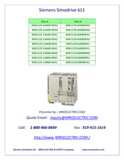
Siemens 6SN1123-1AB00-0CA1 Configuration Manual (485 pages)
SIMODRIVE 611 series Drive Converter
Brand:
Siemens
| Category:
Converters
| Size: 8.97 MB
Table of Contents
Table of Contents
20
Overview of the Drive System
26
Overview of SIMODRIVE 611
26
Engineering Steps
30
Engineering a Drive
32
Calculation of the Required DC Link Power (PZK) for Dimensioning the Supply System, Infeed Unit
34
Dynamic Operation
35
Braking Operation
36
Calculation of the DC Link Power (Engineering Sheet)
37
Checking the Permissible Power Supply Rating
38
System Configuration
42
Arrangement of the Modules and Their Mounting
43
Arrangement of the Modules
43
Mounting and Installing the Modules
46
Ambient Conditions
47
Motor Selection
49
Position Sensing/Actual Speed Value Sensing
50
Position Sensing, Direct
50
Position Detection, Indirect
51
Drive Module
52
Power Modules
52
Function of the Power Modules
53
Connecting-Up the Power Modules
53
Control Units
54
General
54
AC Motors
54
Modules Included in the Scope of Supply
54
NCU Box for SINUMERIK 840D
55
Infeed Modules
56
Cooling Components
58
Internal Cooling
60
External Cooling
61
Motor Selection, Position/Speed Sensing
64
Motor Selection
64
Motor Protection
64
Motors with Holding Brake
64
Motor Encoder
65
Indirect Position and Motor Speed Sensing
69
3.4 Direct Position Sensing
69
Encoder Systems that Can be Evaluated
69
Encoder Power Supply
70
Encoder Power Supply
73
Encoder Power Supply for SSI Encoders
75
Signal Amplifier Electronics
77
Overview, Position Sensing
79
Ordering Information
81
Control Units
82
Closed-Loop Control with Digital Setpoint Interface
84
SIMODRIVE 611 Universal HRS" Control Board
92
Control Board for 1 or 2 Axes
94
Description of the Terminals and Interfaces
99
HLA Module" Control Board
105
System Overview
106
Wiring
108
Test Sockets (Diagnostics)
112
ANA Module" Control Board
113
System Overview
114
Wiring
116
Bus Interfaces
120
Description
122
Operating Modes
124
Technical Data
125
Current Reduction/Derating
129
Pulse Frequency Power Modules
129
Temperature-Dependent Derating
131
Installation Height-Dependent Derating
131
Calculation Examples
132
Operating Power Modules from an Unregulated Infeed
135
Interfaces and Terminals
137
Motor Terminals A1 and A2
139
Infeed Modules
142
Description
142
Interface Overview, NE Modules
148
Kw UI Module Interface Overview
151
Cable Cross-Sections that Can be Connected
153
Three-Conductor Connection (Standard Circuit)
154
Description of the Interfaces and Functions
155
Technical Data
166
General Information
166
Permissible Duty Cycles/Derating
170
Technical Data of the Supplementary Components
173
Assignment of the HFD Reactors/Damping Resistors to the NE Modules
176
Monitoring Module
180
Integration into the Overall System
180
Technical Data (Supplement to the General Technical Data)
180
Mode of Operation
182
DC Link Options
184
Capacitor Module with 2.8 Mf, 4.1 Mf or 20 Mf
184
Pulsed Resistor Module and Unregulated Line Supply Infeed with Pulsed Resistor
192
External Pulsed Resistors
195
And PR Module
198
Line Supply Connection
200
7.1 Line Supply Connection Conditions for Line Supply Infeed
201
Voltage Matching
206
General
206
Line Supply Types
206
Minimum Cross-Sections for PE (Protective Conductor)/Equipotential
210
Bonding Conductor
210
Transformers
211
Assignment of the Line Fuses to the NE Modules
216
Assigning Autotransformers to the I/R Modules
221
Assigning the Main Switches
227
Use of a Leading Contact for Line Isolating Device
227
Line Filters for I/R and UI Modules
231
General Information
231
Wideband Line Filter
233
Basic Line Filter for I/R Modules
236
Adapter Sets
239
Important Circuit Information
240
General Information
240
8.2 Infeed Modules
243
Connecting Several NE Modules to a Main Switch
243
Application, Mode of Operation and Connection of the Line Contactor
244
Timing Diagram for the Ready Signal in the I/R Module
245
Axis Expansion Using a Monitoring Module
246
Connection Example, Power Supply (Standard)
246
Connection Example, Pulse Enable
247
Description of the Interfaces and Functions
248
Description of the Interfaces and Functions
251
Start Inhibithibit Inhibit the Drive Modules/Safe Standstill
253
Mode of Operation of the Start Inhibit
254
Connecting-Up the Start Inhibit
255
Sequence and Timing When Using the Start Inhibit
257
Checking the Start Inhibit
258
Example "Safe Standstill" with Contactor Safety Combination
259
Application Examples with SIMODRIVE 611
263
Safety Systems and Standards
267
Circuit Examples =1 to =9 with SIMODRIVE 611
269
Function Description, Circuit Examples =1 to =9
281
Information and Instructions Regarding Applications
295
With 611 Digital/611 Universal
295
Circuit Example, 611 Digital with SINUMERIK 840D
296
Circuits with 611 Digital
296
Circuits with 611 Universal HRS
297
Master/Slave Operation, SIMODRIVE 611
298
Star-Delta Mode
299
Series Reactor in the Motor Lead
302
Induction Motor Operation
304
Operating Several Induction Motors in Parallel
304
Selecting Individual Induction Motors 611
306
Operation When the Power Fails
308
Application and Mode of Operation
308
Functions
308
DC Link Buffering
311
SINUMERIK Safety Integrated
312
Examples of Correctly and Incorrectly Connecting NE
313
To the Line Supply
313
Six-Conductor Connection to the Line Supply
317
8.16 VPM Voltage Protection Module
323
General Information
323
Integration
325
Mounting
334
Cabinet Design and EMC
336
Installation and Connecting-Up Regulations
336
Shielded Connecting Plates
339
Mounting Conditions, Internal Cooling
342
Two-Tier Equipment Configuration
345
High-Voltage Test in the System
347
Safety of Machinery - Safety-Related Parts of Controls According
348
General Information
348
Safety-Related Stop Functions of Electric Drive Systems According
348
Control Modules Safety-Related Circuit
349
Safety-Related Circuit Infeed Modules
351
Safety Functions
352
Principle of STO in a Safety Function
353
Principle of SS1 in a Safety Function
354
9.4 Application Examples
355
EMERGENCY STOP at a Converter " SS1
355
EMERGENCY STOP and Protective Door Monitoring at a Converter " SS1
361
EMERGENCY STOP and Protective Door at Several Converters " SS1
373
Connection Diagrams
380
11.1 Fan
385
Terminals
387
DC Link Covers
387
Inspection of the DC Link Capacitors of the PM Modules
388
A Abbreviations and Terminology
460
B References
465
Certificates/Declarations of Conformity
466
D Index
481
Advertisement
Advertisement
Related Products
Siemens 6SN11231AA000DA2
Siemens 6SN1123-1AA00-0EA2
Siemens 6SN11231AA000EA1
Siemens 6SN1123-1AA00-0JA1
Siemens 6SN1123-1AA00-0LA1
Siemens 6SN1123-1AB00-0BA0
Siemens 6SN1123-1AB00-0BA1
Siemens 6SN1123-1AA00-0EA0
Siemens SIMOTRAS 6SG7052
Siemens 6SL3210-1KE21-7UF1
Siemens Categories
Industrial Equipment
Controller
Control Unit
Oven
Washer
More Siemens Manuals
Login
Sign In
OR
Sign in with Facebook
Sign in with Google
Upload manual
Upload from disk
Upload from URL