Sign In
Upload
Manuals
Brands
Panasonic Manuals
Fax Machine
KX-FL513RU
Panasonic KX-FL513RU Manuals
Manuals and User Guides for Panasonic KX-FL513RU. We have
2
Panasonic KX-FL513RU manuals available for free PDF download: Service Manual
Panasonic KX-FL513RU Service Manual (266 pages)
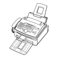
High Speed Laser Fax and Copier
Brand:
Panasonic
| Category:
Fax Machine
| Size: 6.67 MB
Table of Contents
Table of Contents
2
Operation Cover Section
2
Lower Main Cabinet Section
2
1 Introduction
4
Translation Lists
4
ABOUT LEAD FREE SOLDER (Pbf: Pb Free)
6
HOW to RECOGNISE that Pb FREE SOLDER IS USED
7
Safety Precautions
8
Insulation Resistance Test
8
For Service Technicians
8
Battery Caution
8
Ac Caution
9
Personal Safety Precautions
9
Service Precautions
11
For Best Performance
11
2 Features and Specifications
12
Features
12
Specifications
13
Optional Accessories
13
3 Installation
14
Location of Controls
14
Connections
16
Installation
17
Installation Space
17
Paper Stacker
18
Document Stacker
18
Paper Tray
19
Installing the Recording Paper
20
Setting Your Logo
24
Replacing the Toner Cartridge and the Drum Unit
25
4 Maintenance
29
Maintenance Items and Component Locations
29
Printing
31
Printing (Paper Pick Up)
32
Scanning (Adf)
33
Maintenance
34
Cleaning the Inside of the Unit
34
Document Jams
37
Recording Paper Jams
38
5 Disassembly Instructions
41
Upper Main Cabinet Section
42
Lower Main Cabinet Section
43
How to Remove the Operation Panel Ass'y
44
How to Remove the Pick up Unit
45
How to Remove the Pick up Roller
46
How to Remove the Operation Board
47
How to Remove the Lower Flame
48
How to Remove the Separation Rubber
48
How to Remove the Transfer Roller
49
How to Remove the Separation Roller
50
How to Remove the Bottom Plate
51
How to Remove the Analog Board
51
How to Remove the High Voltage Power Board
52
How to Remove the Laser Unit
52
How to Remove the Fan Unit
53
How to Remove the Low Voltage Power Board
53
How to Remove the Solenoid
54
How to Remove the Handset Holder
54
How to Remove the Main Motor
55
How to Remove the Fuser Unit
56
How to Remove the Cis
57
Note for Assembling
58
Installation Position of the Lead
59
6 Troubleshooting Guide
60
User Recoverable Errors
60
Programming and Lists
62
Operation Flow
62
Test Functions
65
Print Test Pattern
68
Remote Programming
69
Troubleshooting Details
77
Light Print
94
Operation Panel Section
132
Adf Motor
137
7 Circuit Operations
148
Connection Diagram
148
General Block Diagram
149
Facsimile Section
151
Description of Block Diagram in Analog Section
160
Ncu Section
162
ITS (Integrated Telephone System) and MONITOR SECTION
164
Tam Interface Section
165
Cis Control Section
166
Stepping Motor Drive Section
167
Timing Chart
169
Fan Motor Section
171
Solenoid Drive Section
173
LSU (Laser Scanning Unit) SECTION
174
Sensors and Switches Section
176
Operation Board Section
185
Lcd Section
186
HVPS (High Voltage Power Supply) SECTION
187
Heat Lamp Control Circuit
189
Power Supply Board Section
195
8 Reference Materials Data
198
Printing Operation Principle
198
TERMINAL GUIDE of the Ics TRANSISTORS and DIODES
206
How to Replace the Flat Package IC
207
Flat Package IC Installation Procedure
208
Bridge Modification Procedure
208
Digital Board Section
209
Modem Section
211
Test Chart
217
9 Fixtures and Tools
219
Cabinet, Mechanical and Electrical Parts
220
10 Cabinet, Mechanical and Electrical Parts Location
220
General Section
220
Operation Cover Section
221
Operation Cover Section
223
Pick up Section
224
Fuser Section
225
Upper Main Cabinet Section
226
Lower Main Cabinet Section
227
Lower Cabinet Section
229
Actual Size of Screws and Washer
230
11 Accessories and Packing Materials
231
12 Replacement Parts List
232
Cabinet and Electrical Parts
232
Accessories and Packing Materials
234
Digital Board Parts
234
Analog Board Parts
237
Operation Board Parts
239
High Voltage Power Supply Board Parts
240
Low Voltage Power Supply Board Parts
240
Exit Sensor Board Parts
241
Drum and Toner Sensor Board Parts
241
Varistor Board Parts
241
Fixtures and Tools
241
13 For the Schematic Diagrams
243
14 Schematic Diagram
244
Digital Board (Pcb1)
244
15 Schematic Diagram
248
Analog Board (Pcb2)
248
Operation Board (Pcb3)
250
High Voltage Power Supply Board (Pcb4)
252
Low Voltage Power Supply Board (Pcb5)
253
Exit Sensor Board (Pcb6)
254
Drum and Toner Sensor Board (Pcb7)
254
Varistor Board (Pcb8)
254
16 Printed Circuit Board
255
Digital Board (Pcb1)
255
Analog Board (Pcb2)
257
Operation Board (Pcb3)
259
High Voltage Power Supply Board (Pcb4)
261
Low Voltage Power Supply Board (Pcb5)
263
Exit Sensor Board Parts (Pcb6)
265
Drum and Toner Sensor Board (Pcb7)
265
Varistor Board (Pcb8)
265
Advertisement
Panasonic KX-FL513RU Service Manual (6 pages)
High Speed Laser Fax and Copier
Brand:
Panasonic
| Category:
Copier
| Size: 0.15 MB
Advertisement
Related Products
Panasonic KX-FL511AL
Panasonic KX-FL511
Panasonic KX-FL511E
Panasonic KX FL511 - B/W Laser - Fax
Panasonic KX-FL511C
Panasonic KX-FL541
Panasonic KX-FL501C
Panasonic KX-FL501AL
Panasonic KX-FL501E
Panasonic KX FL501 - B/W Laser - Fax
Panasonic Categories
Camcorder
Air Conditioner
TV
Digital Camera
Cordless Telephone
More Panasonic Manuals
Login
Sign In
OR
Sign in with Facebook
Sign in with Google
Upload manual
Upload from disk
Upload from URL