Sign In
Upload
Manuals
Brands
Mitsubishi Electric Manuals
Heat Pump
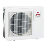
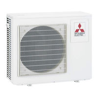
Mr.Slim PUHZ-ZRP125YKA
Mitsubishi Electric Mr.Slim PUHZ-ZRP125YKA Manuals
Manuals and User Guides for Mitsubishi Electric Mr.Slim PUHZ-ZRP125YKA. We have
2
Mitsubishi Electric Mr.Slim PUHZ-ZRP125YKA manuals available for free PDF download: Service Manual
Mitsubishi Electric Mr.Slim PUHZ-ZRP125YKA Service Manual (144 pages)
SPLIT-TYPE, HEAT PUMP AIR CONDITIONERS R410A
Brand:
Mitsubishi Electric
| Category:
Heat Pump
| Size: 18.28 MB
Table of Contents
Table of Contents
1
Service Manual
1
Cautions Related to New Refrigerant
2
Indoor Unit Service Manual
2
Reference Manual
2
Safety Precaution
2
Additional Refrigerant Charge
3
Cautions for Service
3
Precautions When Reusing Existing R22 Refrigerant Pipes
4
Refrigerant Leakage Detection Function
4
Service Tools
4
Cautions for Refrigerant Piping Work
5
Dimensions of Flare Cutting and Flare Nut
5
Thickness of Pipes
5
Tools for R410A
5
Features
6
Specifications
7
Compressor Technical Data
9
Data
9
Refilling Refrigerant Charge
9
Noise Criterion Curves
10
Puhz-Zrp100Vka
10
Puhz-Zrp100Yka
10
Puhz-Zrp35Vka
10
Puhz-Zrp50Vka
10
Puhz-Zrp60Vha
10
Puhz-Zrp71Vha
10
Standard Operation Data
11
Outlines and Dimensions
13
Puhz-Zrp125Vka
15
Puhz-Zrp125Yka
15
Puhz-Zrp140Vka
15
Puhz-Zrp140Yka
15
Wiring Diagram
16
Field Electrical Wiring
20
Wiring Specifications
20
Separate Indoor Unit/ Outdoor Unit Power Supplies
21
Indoor – Outdoor Connecting Cable
22
M-Net Wiring Method
23
M-NET Address Setting
24
Refrigerant Address Setting
24
Regulations in Address Settings
24
Refrigerant System Diagram
25
Refrigerant Collecting (Pump Down)
27
Start and Finish of Test Run
27
Before Test Run
28
Check Point under Test Run
28
Troubleshooting
28
Auto Vane Check
29
Test Run for Wired Remote Controller
29
Test Run Operation
29
Error Information
30
Checking the Error Information
31
Deleting the Error History
31
Error History
31
Operating Procedures
32
Test Run for Wireless Remote Controller
33
How to Proceed "Self-Diagnosis"
34
Resetting the Error History.
34
Remote Controller Check
35
Self-Diagnosis During Maintenance or Service
36
Remote Controller Diagnosis
37
Self-Diagnosis Action Table
40
Troubleshooting of Problems
52
PLEASE WAIT Is Kept Being Displayed on the Remote Controller
54
Nothing Is Displayed on the Remote Controller
55
How to Check the Parts
62
Check Method of DC Fan Motor
63
How to Check the Components
64
Low Temperature Thermistors
64
Medium Temperature Thermistor
64
Thermistor Feature Chart
64
Linear Expansion Valve
65
Linear Expansion Valve Operation
65
Output Pulse Signal and the Valve Operation
65
Operation Summary of the Linear Expansion Valve
66
How to Attach and Detach the Coil of Linear Expansion Valve
67
Emergency Operation
69
Releasing Emergency Operation
69
Operation Data During Emergency Operation
70
Test Point Diagram
71
Outdoor Controller Circuit Board
72
Outdoor Noise Filter Circuit Board
73
Outdoor Power Circuit Board
75
Outdoor Converter Circuit Board
78
Outdoor M-NET Board (Optional)
79
Function of Connector
81
Low-Level Sound Priority Mode (Local Wiring)
81
On Demand Control (Local Wiring)
81
Special Function
81
Display Function of Inspection for Outdoor Unit
82
Digital Indicator LED1 Working Details
84
Display During Error Postponement
84
Outdoor Unit Operation Monitor Function
84
Function Setting
93
Meaning of "Function Setting"
93
Unit Function Setting by the Remote Controller
93
Selecting Functions Using the Wired Remote Controller
95
Service Menu
95
Operating Procedure
98
Selecting Functions Using the Wireless Remote Controller
99
Function Selection of Remote Controller
100
Menu Structure of PAR-30MAA/PAR-31MAA
101
Main Menu List of PAR-30MAA/PAR-31MAA
102
Par-21Maa
104
CHANGE LANGUAGE Setting
105
Function Limit
105
Temperature Range Limit Setting
105
Use of Automatic Mode Setting
105
How to "Monitor the Operation Data"
106
Monitoring the Operation Data by the Remote Controller
106
Canceling the Monitoring the Operation Data
107
Operating the Service Inspection Monitor
107
Request Code List
108
Detail Contents in Request Code
112
Easy Maintenance Function
117
Smooth Maintenance
117
Fixed Hz Operation
118
Maintenance Mode Operation Method
118
Switching to Maintenance Mode
118
Data Measurement
119
Refrigerant Address
119
Cool Mode
120
Guide for Opration Condition
120
Heat Mode
120
Refrigerant Leak Check
121
Remote Controller Button Position
122
How to Reset the Initial Condition (Data)
123
How to Start "Judgment of Refrigerant Leakage " Mode
123
Disassembly Procedure
124
Removing the Fan Motor
124
Removing Top Panel, Service Panel, Front Panel, Back Panel and Grille
124
Removing the Electrical Parts Box
125
Removing the Thermistor
125
Removing LEV
127
Removing the 4-Way Valve
127
Removing the High Pressure Switch
127
Removing the Reactor
127
Removing the Compressor (MC)
128
Removing the Power Receiver
128
Removing the Fan Motor (MF1)
129
Removing the Service Panel and Top Panel
129
Removing the 4-Way Valve Coil
131
Removing the LEV
131
Disassembling the Electrical Parts Box
140
Removing the Compressor
144
Advertisement
Mitsubishi Electric Mr.Slim PUHZ-ZRP125YKA Service Manual (146 pages)
Brand:
Mitsubishi Electric
| Category:
Air Conditioner
| Size: 12.26 MB
Table of Contents
Table of Contents
1
Reference Manual
2
Safety Precaution
2
Service Ref
2
Technical Changes
2
Features
6
Specifications
7
Data
9
Puhz-Zrp140Vka
9
Puhz-Zrp100Vka
10
Puhz-Zrp100Yka
10
Puhz-Zrp100Ykar1
10
Puhz-Zrp35Vka
10
Puhz-Zrp50Vka
10
Puhz-Zrp60Vha
10
Puhz-Zrp71Vha
10
Puhz-Zrp125Vka Puhz-Zrp125Yka
12
Outlines and Dimensions
13
Puhz-Zrp125Ykar1
15
Puhz-Zrp140Yka
15
Wiring Diagram
16
Wiring Specifications
21
Refrigerant System Diagram
26
Troubleshooting
29
Function Setting
95
Monitoring the Operation Data by the Remote Controller
108
Easy Maintenance Function
119
Disassembly Procedure
126
A Wet Cloth to Prevent It from Heating
129
Pipes Are Not Oxidized
129
Remove the Service Panel. (See Photo 1) (2) Remove the Top Panel. (See Photo 1) (3) Remove the Electrical Parts Box. (See Photo 4)
134
Remove the Service Panel. (See Photo 1)
139
Remove the Top Panel. (See Photo 1)
139
Remove the Electrical Parts Box. (See Photo 4)
139
Remove 3 Valve Bed Fixing Screws (4 × 10) and 4 Ball
139
Remove 3 Right Side Panel Fixing Screws (5 × 12) in the
139
Rear of the Unit then Remove the Right Side Panel
139
Recover Refrigerant
139
Note 1: Recover Refrigerant Without Spreading It in the Air
139
Remove the Top Panel. (See Photo 1)
143
(LEV (A), LEV (B)), (LEV (C) :140 Only)
144
Remove the Service Panel. (See Photo 1) Coil (21S4)
144
[Removing the 4-Way Valve Coil] (3) Remove 4-Way Valve Coil Fixing Screw (M4 × 6). (4) Remove the 4-Way Valve Coil by Sliding the Coil Toward You
144
Disconnect the Connector 21S4 (Green) on the Controller Circuit Board in the Electrical Parts Box
144
[Removing the LEV Coil] (3) Remove the LEV Coil by Sliding the Coil Upward
144
Disconnect the Connectors, LEV a (White) and LEV B (Red), LEV C (Blue) on the Controller Circuit Board in the Electrical Parts Box
144
Removing the 4-Way Valve
144
Valve and Stop Valve Fixing Screws (5 × 16) then Remove
144
The Valve Bed
144
Remove the 4-Way Valve Coil
144
Advertisement
Related Products
Mitsubishi Electric Mr.Slim PUHZ-SHW-HA
Mitsubishi Electric Mr.Slim PUHZ-SHW-KA
Mitsubishi Electric Mr.Slim PUHZ-ZRP100VKA
Mitsubishi Electric Mr.Slim PUHZ-ZRP35VKA
Mitsubishi Electric Mr.Slim PUHZ-ZRP125VKA
Mitsubishi Electric Mr.Slim PUHZ-ZRP140VKA
Mitsubishi Electric Mr.Slim PUHZ-ZRP100YKA
Mitsubishi Electric Mr.Slim PUHZ-ZRP50VKA
Mitsubishi Electric Mr.Slim PUHZ-ZRP140YKA
Mitsubishi Electric Mr.Slim PUHZ-ZRP60VHA
Mitsubishi Electric Categories
Air Conditioner
Controller
Projector
Inverter
Heat Pump
More Mitsubishi Electric Manuals
Login
Sign In
OR
Sign in with Facebook
Sign in with Google
Upload manual
Upload from disk
Upload from URL